Product Introduction:Sige5
Let's get to know Sige5 in 5 minutes.
Overview
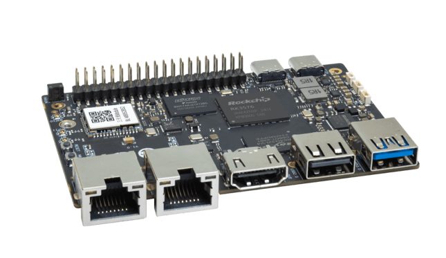
ArmSoM-Sige5 adopts the second-generation 8nm high-performance AIOT platform Rockchip RK3576, with a 6 TOPS computing power NPU and support for up to 16GB of large memory. It supports 4K video encoding and decoding, offers rich interfaces including dual gigabit Ethernet ports, WiFi 6 & BT5, and various video outputs. Compatible with multiple operating systems, it is suitable for ARM-based PCs, edge computing devices, personal mobile internet devices, and other digital multimedia applications.
Key Parameter
- SoC: Rockchip RK3576
- CPU: Integrated with four Cortex-A72 cores @ 2.2GHz and four Cortex-A53 cores @ 1.8GHz, along with a separate NEON co-processor.
- GPU: ARM Mali G52 MC3 GPU
- NPU: Up to 6 TOPs computing power (INT8), supports INT4/INT8/INT16 mixed operations.
- VPU/Encoding & Decoding:
- Hardware Decoding: Supports H.264, H.265, VP9, AV1, and AVS2 up to 8K@30fps or 4K@120fps.
- Hardware Encoding: Supports H.264 and H.265 up to 4K@60fps, high-quality JPEG encoder/decoder supports up to 4K@60fps.
- RAM: 8/16GB 32-bit LPDDR4x, default is 16GB. RK3576 supports a maximum of 16GB.
- Flash: 32/128GB eMMC, default is 128GB eMMC.
- Operating Voltage: Wide input voltage range, from 4.5V to 23V (voltage error ±5%).
- Operating Temperature: 0°C to 80°C
- Operating Systems:
- Official Rockchip Support: Android 14, Debian 11, Buildroot
- Third-party Support: Armbian
- PCB: 8-layer PCB board design
- Weight: 43g
- Dimensions: 92mm × 62mm
Hardware
Hardware Interface
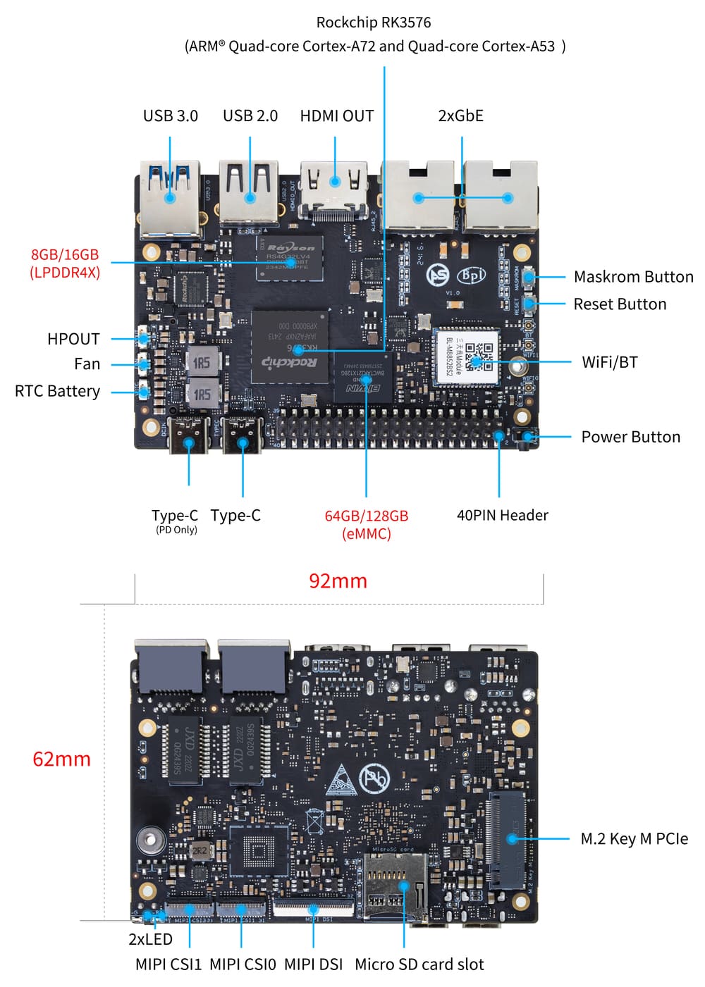
There are two identical Type-C ports on Sige5,but only the Type-C (PD Only) port is for power input.
Hardware Spec
| Category | Functional Parameters |
|---|---|
| SOC | |
| CPU | |
| GPU | |
| NPU | |
| VPU/Codec | |
| ISP | |
| RAM | |
| Flash | |
| PCIe | |
| Network | |
| Video Output | |
| Video In | |
| Audio | |
| USB Ports | |
| 40-pin | |
| Other | |
| Power Input | |
| Buttons | |
| OS Support | |
| Dimensions | |
| Operating temperature |
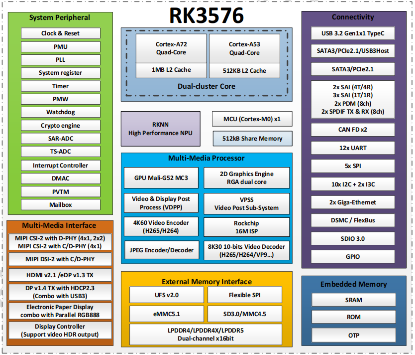
RK3576 Block Diagram
Hardware Pin Definitions
40-pin header
| GPIO number | Function | Pin | Pin | Function | GPIO number |
|---|---|---|---|---|---|
| +3.3V | 1 | 2 | +5.0V | ||
| 111 | I2C4_SDA_M3 /UART3_CTSN_M1/UART2_RX_M2/GPIO3_B7_d/ | 3 | 4 | +5.0V | |
| 112 | I2C4_SCL_M3/UART3_RTSN_M1 /UART2_TX_M2/GPIO3_C0_d | 5 | 6 | GND | |
| 100 | PWM1_CH0_M3 / SPI2_CLK_M2 / UART1_CTSN_M2 / GPIO3_A4_d | 7 | 8 | GPIO0_D4_u / UART0_TX_M0_PORT / JTAG_TCK_M1 | 28 |
| GND | 9 | 10 | GPIO0_B6/ UART0_RX_M0 /JTAG_TMS_M1 | 14 | |
11 | 12 | SAI0_SCLK_M1 / SPI0_CSN0_M0 / I2C3_SCL_M1 / GPIO0_C6_d | 22 | ||
13 | 14 | GND | |||
15 | 16 | I2C8_SDA_M2 / UART7_RX_M0 / SAI0_LRCK_M0 / GPIO2_B7_d | 79 | ||
| +3.3V | 17 | 18 | I2C8_SCL_M2 / UART7_TX_M0 / GPIO2_B6_d | 78 | |
| 149 | SPI4_MOSI_M0 / PWM2_CH5_M1 /UART6_RX_M3 / I2C3_SDA_M3/GPIO4_C5_d | 19 | 20 | GND | |
| 150 | PWM2_CH2_M1/CAN1_TX_M1 /SPI4_MISO_M0/I2C6_SCL_M3 / GPIO4_C6_d | 21 | 22 | SARADC_VIN4 | |
| 151 | PWM2_CH3_M1/CAN1_RX_M1/SPI4_CLK_M0/I2C6_SDA_M3/ GPIO4_C7_d | 23 | 24 | PWM2_CH6_M1 / UART6_TX_M3 /SPI4_CSN0_M0/ GPIO4_C4_d | 148 |
| GND | 25 | 26 | |||
| 104 | PWM0_CH0_M3 / SPI2_MOSI_M2 / UART10_RX_M0 / GPIO3_B0_d | 27 | 28 | GPIO2_D6_D/PWM2_CH6_M2 / UART9_RTSN_M0 | |
| 119 | GPIO3_C7_D / UART8_RTSN_M0 | 29 | 30 | GND | |
| 128 | GPIO3_D4_D/ I2C3_SCL_M2 / SPI3_CLK_M1 / UART5_RX_M0 | 31 | 32 | ||
| 95 | PWM2_CH7_M2/SPI3_CSN1_M0/UART9_CTSN_M0/SPDIF_TX0_M2/GPIO2_D7_d | 33 | 34 | GND | |
| 20 | PWM0_CH0_M0/UART10_TX_M2/PDM0_CLK0_M0/SAI0_MCLK_M1/GPIO0_C4_d | 35 | 36 | SPI0_CLK_M0/I2C3_SDA_M1/SAI0_LRCK_M1/GPIO0_C7_d | 23 |
| 96 | I2C7_SCL_M1/SPI3_CLK_M0/ UART3_TX_M0/ GPIO3_A0_d D | 37 | 38 | SPI0_MOSI_M0/PDM0_SDI0_M0/SAI0_SDI0_M1/GPIO0_D0_d | 24 |
| GND | 39 | 40 | I3C0_SDA_PU_M0/UART10_RX_M2/ DP_HPDIN_M1/ SAI0_SDO0_M1 / GPIO0_C5_d | 21 |
MIPI CSI0
0.5mm FPC connector
| Pin | MIPI-CSI | Description |
|---|---|---|
| 1,4,7,10,13,16,24,25,26,27,32,33 | GND | Power Ground & Signal Ground |
| 2 | MIPI_DPHY_CSI1_RX_D3N | MIPI RX Lane3 iuput N |
| 3 | MIPI_DPHY_CSI1_RX_D3P | MIPI RX Lane3 iuput P |
| 5 | MIPI_DPHY_CSI1_RX_D2N | MIPI RX Lane2 iuput N |
| 6 | MIPI_DPHY_CSI1_RX_D2P | MIPI RX Lane2 iuput P |
| 8 | MIPI_DPHY_CSI2_RX_CLKN | MIPI RX Clock iuput N |
| 9 | MIPI_DPHY_CSI2_RX_CLKP | MIPI RX Clock iuput P |
| 11 | MIPI_DPHY_CSI1_RX_D1N | MIPI RX Lane1 iuput N |
| 12 | MIPI_DPHY_CSI1_RX_D1P | MIPI RX Lane1 iuput P |
| 14 | MIPI_DPHY_CSI1_RX_D0N | MIPI RX Lane0 iuput N |
| 15 | MIPI_DPHY_CSI1_RX_D0P | MIPI RX Lane0 iuput P |
| 17 | MIPI_DPHY_CSI1_RX_CLKN | MIPI RX Clock iuput N |
| 18 | MIPI_DPHY_CSI1_RX_CLKP | MIPI RX Clock iuput P |
| 19 | MIPI_CSI1_RX_XVS | |
| 20 | MIPI_DPHY_CSI2_CAM_CLKOUT_CON | 1.8V, CLock ouput for Sensor |
| 21 | MIPI_CSI1_RX_XHS | |
| 22 | MIPI_DPHY_CSI1_CAM_CLKOUT | 1.8V, CLock ouput for Sensor |
| 23 | MIPI_DPHY_CSI1_PDN_H(GPIO3_D0) | 1.8V, GPIO |
| 24 | I2C5_SCL_M3_MIPI_CSI1 | 1.8V, I2C Clock, pulled up to 1.8V with 2.2K on sige5 |
| 25 | I2C5_SDA_M3_MIPI_CSI1 | 1.8V, I2C Clock, pulled up to 1.8V with 2.2K on sige5 |
| 26 | MIPI_DPHY_CSI2_PDN_H(GPIO3_C7) | 1.8V, GPIO |
| 27 | MIPI_DPHY_CSI1/2_RST(GPIO3_C6) | 3.3V, GPIO |
| 28,29 | VCC_RX | 3.3V Power ouput |
| 30,31 | VCC_5V0 | 5V Power ouput |
MIPI CSI1
0.5mm FPC connector
| Pin | MIPI-CSI | Description |
|---|---|---|
| 1,4,7,10,13,16,24,25,26,27,32,33 | GND | Power Ground & Signal Ground |
| 2 | MIPI_DPHY_CSI3_RX_D3N | MIPI RX Lane3 iuput N |
| 3 | MIPI_DPHY_CSI3_RX_D3P | MIPI RX Lane3 iuput P |
| 5 | MIPI_DPHY_CSI3_RX_D2N | MIPI RX Lane2 iuput N |
| 6 | MIPI_DPHY_CSI3_RX_D2P | MIPI RX Lane2 iuput P |
| 8 | MIPI_DPHY_CSI4_RX_CLKN | MIPI RX Clock iuput N |
| 9 | MIPI_DPHY_CSI4_RX_CLKP | MIPI RX Clock iuput P |
| 11 | MIPI_DPHY_CSI3_RX_D1N | MIPI RX Lane1 iuput N |
| 12 | MIPI_DPHY_CSI3_RX_D1P | MIPI RX Lane1 iuput P |
| 14 | MIPI_DPHY_CSI3_RX_D0N | MIPI RX Lane0 iuput N |
| 15 | MIPI_DPHY_CSI3_RX_D0P | MIPI RX Lane0 iuput P |
| 17 | MIPI_DPHY_CSI3_RX_CLKN | MIPI RX Clock iuput N |
| 18 | MIPI_DPHY_CSI3_RX_CLKP | MIPI RX Clock iuput P |
| 19 | MIPI_CSI3_RX_XVS | |
| 20 | MIPI_DPHY_CSI4_CAM_CLKOUT_CON | 1.8V, CLock ouput for Sensor / GPIO |
| 21 | MIPI_CSI3_RX_XHS | |
| 22 | MIPI_DPHY_CSI3_CAM_CLKOUT | 1.8V, CLock ouput for Sensor |
| 23 | MIPI_DPHY_CSI3_PDN_H | 1.8V, GPIO |
| 24 | I2C4_SCL_M3_MIPI_CSI3 | 1.8V, I2C Clock, pulled up to 1.8V with 2.2K on sige5 |
| 25 | I2C4_SDA_M3_MIPI_CSI3 | 1.8V, I2C Clock, pulled up to 1.8V with 2.2K on sige5 |
| 26 | MIPI_DPHY_CSI4_PDN_H | 1.8V, GPIO |
| 27 | MIPI_DPHY_CSI3/4_RST | 3.3V, GPIO |
| 28,29 | VCC_RX | 3.3V Power ouput |
| 30,31 | VCC_5V0 | 5V Power ouput |
MIPI DSI
0.5mm FPC connector
| Pin | MIPI-DSI | Description |
|---|---|---|
| 1,4,7,10,13,16,27,33,34 | GND | Power and Signal Ground |
| 2 | MIPI_DPHY_DSI_TX_D0N | MIPI1 TX Lane0 ouput N |
| 3 | MIPI_DPHY_DSI_TX_D0P | MIPI1 TX Lane0 ouput P |
| 5 | MIPI_DPHY_DSI_TX_D1N | MIPI1 TX Lane1 ouput N |
| 6 | MIPI_DPHY_DSI_TX_D1P | MIPI1 TX Lane1 ouput P |
| 8 | MIPI_DPHY_DSI_TX_CLKN | MIPI1 TX Clock ouput N |
| 9 | MIPI_DPHY_DSI_TX_CLKP | MIPI1 TX Clock ouput P |
| 11 | MIPI_DPHY_DSI_TX_D2N | MIPI1 TX Lane2 ouput N |
| 12 | MIPI_DPHY_DSI_TX_D2P | MIPI1 TX Lane2 ouput P |
| 14 | MIPI_DPHY_DSI_TX_D3N | MIPI1 TX Lane3 ouput N |
| 15 | MIPI_DPHY_DSI_TX_D3P | MIPI1 TX Lane3 ouput P |
| 17 | LCD_BL_PWM1_CH1_M0 | 1.8V, GPIO/PWM |
| 18,19 | VCC3V3_LCD | 3.3V Power ouput |
| 20 | LCD_RESET | 1.8V, GPIO |
| 21 | /NC | No Connection |
| 22 | LCD_BL_EN_H | 3.3V, GPIO |
| 23 | I2C0_SCL_M1_TP | 1.8V, I2C Clock, pulled up to 1.8V with 2.2K on sige5 |
| 24 | I2C0_SDA_M1_TP | 1.8V, I2C Data, pulled up to 1.8V with 2.2K on sige5 |
| 25 | TP_INT_L | 1.8V, GPIO |
| 26 | TP_RST_L | 1.8V, GPIO |
| 28,29 | VCC5V0_LCD | 5V Power ouput |
| 31,32 | VCC_1V8 | 1.8V Power ouput |
Fan
0.8mm connector(CON3102)
| Pin | Assignment | Description |
|---|---|---|
| 1 | VCC_5V0 | 5V Power ouput |
| 2 | GND | GND |
| 3 | PWM | PWM control |
Resources
Source Code
ArmSoM github source code : https://github.com/ArmSoM/armsom-build
ArmSoM-Sige5 kernel:
ArmSoM-Sige5 uboot:
openwrt(istoreos): https://github.com/istoreos/istoreos
Official Image
ArmSoM team uses Debian bullseye as the official operating system.
Download
The following systems have been tested and verified by ArmSoM official:
Network disk address: Google Drive link
debain bullseye
Firmware location: 3. Linux image/debian/ArmSoM-sige5 -
Third Party System
Ubuntu
Image location: 3. Linux Images/ubuntu/ArmSoM-sige5 -
istoreos
Firmware location: 3. Linux image/openwrt/ArmSoM-sige5 -
armbian

Firmware location: 3. Linux image/armbian/ArmSoM-sige5 -
Hardware Resources
The sige5 user manual helps users understand the basic operation of sige5 and the necessary preparations. When you receive the product, you need to know its model and hardware version, which can be found on the board's silk screen. We will introduce the product information to you in as much detail as possible.
Getting Started
Before using ArmSoM-sige5, please prepare the following items:
Tools Preparation
- sige5 mainboard
- Power supply: USB Type-C PD
- Supports 9V/2A, 12V/2A, 15V/2A
- System installation (choose one):
- MicroSD card/TF card boot
- MicroSD card/TF card, Class 10 or above, at least 8GB SDHC, and a card reader
- The following are high-speed TF cards verified and tested by the ArmSoM team:
- SanDisk 32GB TF (MicroSD) (recommended for developers)
- SanDisk 32GB TF (MicroSD) for dashcams & surveillance cameras (recommended for long-term use)
- SanDisk TF 8G Class10 microSD
- SanDisk TF 128G Class10 microSD XC TF 128G 48MB/S
- Onboard eMMC boot
- USB Type-C data cable, to write the image from the type-C port on sige5, you need a Type-C data cable to connect sige5 and PC.
- MicroSD card/TF card boot
Optional Accessories
- USB keyboard and mouse
- HDMI monitor and HDMI cable
- sige5 comes with a full-size HDMI port, supporting up to 8K@60 display.
- HDMI EDID is used to determine the optimal display resolution. On monitors and TVs that support 1080p (or 4K/8K), this resolution will be chosen. If 1080p is not supported, EDID will find the next available resolution.
- Ethernet cable (network cable)
- sige5 supports Ethernet networking, with a maximum of 2.5Gb.
- The network cable is used to connect sige5 to the local network and the Internet.
- Camera module
- sige5 supports camera function.
- It is recommended to use the imx415 module, which can be purchased from the official ArmSoM store on Taobao.
- LCD display
- sige5 supports LCD display function.
- It is recommended to use the ArmSoM Display 10.1 HD, which can be purchased from the official ArmSoM store on Taobao.
- Audio cable
- A 0.8mm vertical socket can be used.
- USB-A to USB-C data cable
Choosing the Burning Method
Interface Settings
If you are using ArmSoM-sige5 for the first time, please familiarize yourself with the Peripheral Interfaces for better understanding of the following content.
Debug Serial Port
Connect the USB to TTL serial cable as follows:
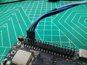
| sige5 | Connect | Serial Module |
|---|---|---|
| GND (pin 6) | <---> | GND |
| TX (pin 8) | <---> | RX |
| RX (pin 10) | <---> | TX |
Gigabit Ethernet Port
If you are using a wired Ethernet connection for internet access, please insert the Ethernet cable into the RJ45 port on ArmSoM-sige5. The system desktop will then prompt a wired connection.
- Use the command
ifconfigto check if the Ethernet is working properly. It will display the network cardenP2p33s0orenP4p65s0and the Ethernet IP address. Additionally, use thepingtool to check network connectivity.
ifconfig
ping mi.com
- If ping fails, try:
$ sudo dhclient enP2p33s0
or
$ sudo dhclient enP4p65s0
WIFI
# 1. Open the WIFI
armsom@armsom-sige5:/# nmcli r wifi on
# 2. Scan WIFI
armsom@armsom-sige5:/# nmcli dev wifi
# 3. Connect to WIFI network
armsom@armsom-sige5:/# nmcli dev wifi connect "wifi_name" password "wifi_password"
BT
# 1. Activate Bluetooth
armsom@armsom-sige5:/# service bluetooth start
# 2. Enter bluetoothctl
armsom@armsom-sige5:/# bluetoothctl
# 3. Enter the following command to connect
armsom@armsom-sige5:/# power on
armsom@armsom-sige5:/# agent on
armsom@armsom-sige5:/# default-agent
armsom@armsom-sige5:/# scan on
armsom@armsom-sige5:/# pair yourDeviceMAC
HDMI
The ArmSoM-Sige5 has an HDMI output port which supports CEC and HDMI 2.1, maximum resolution up to 4Kp120.
USB
The ArmSoM-Sige5 provides one USB 2.0 and one USB 3.0 port.
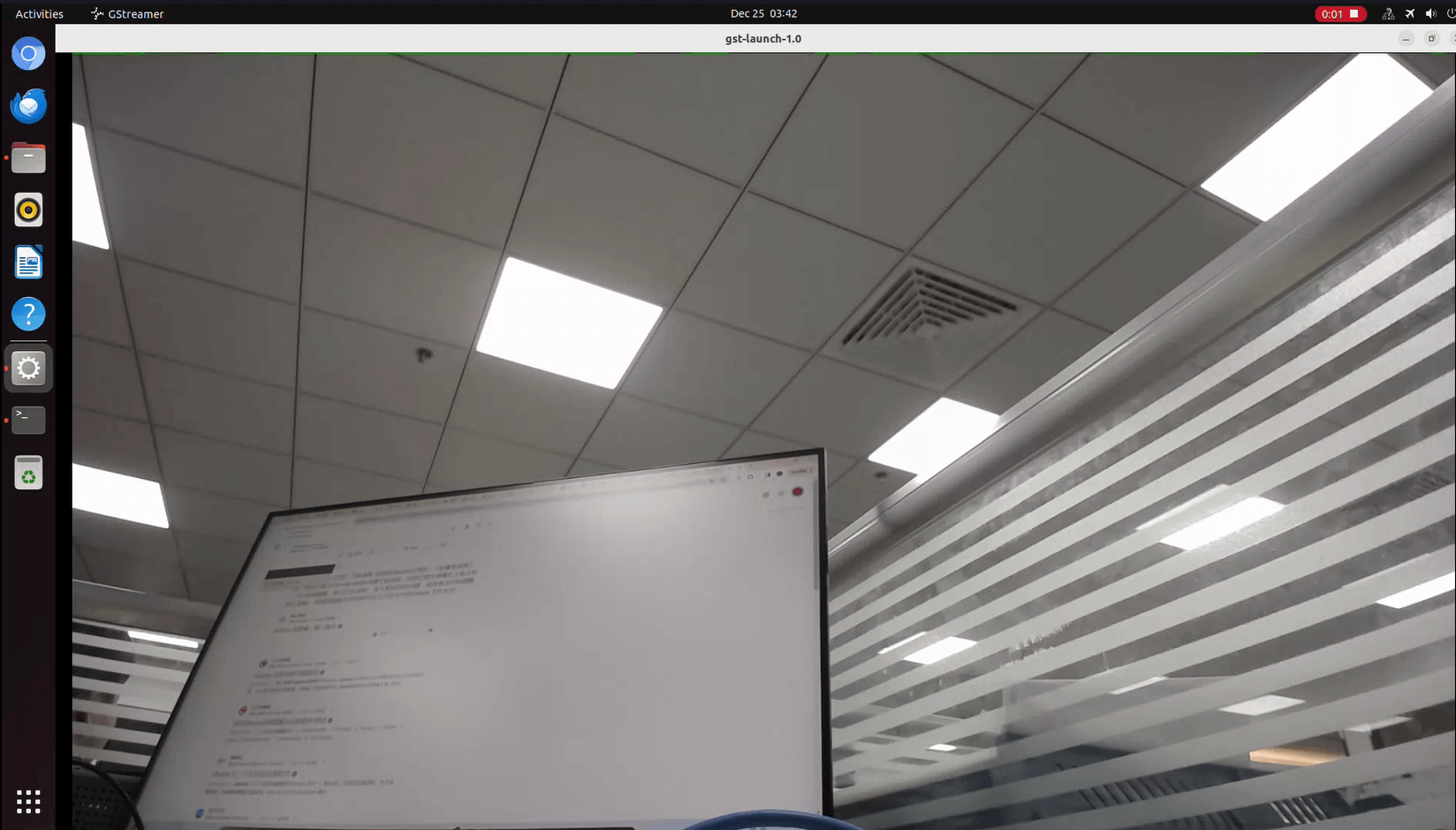
USB3.0 Camera
After connecting a USB 3.0 camera, you can download cheese and use the camera with the following commands:
armsom@armsom-sige5: sudo apt update
armsom@armsom-sige5: sudo apt install cheese
You can also preview the camera in the terminal:
gst-launch-1.0 v4l2src device=/dev/video0 io-mode=4 ! videoconvert ! video/x-raw,format=NV12,width=1920,height=1080 ! xvimagesink;
Take Photo:
gst-launch-1.0 v4l2src device=/dev/video0 io-mode=4 ! videoconvert ! video/x-raw,format=NV12,width=1920,height=1080 ! jpegenc ! multifilesink location=/home/armsom/test.jpg;
Record video:
gst-launch-1.0 v4l2src num-buffers=512 device=/dev/video0 io-mode=4 ! videoconvert ! video/x-raw, format=NV12, width=1920, height=1080, framerate=30/1 ! tee name=t ! queue ! mpph264enc ! queue ! h264parse ! mpegtsmux ! filesink location=/home/armsom/test.mp4
Audio
View sound cards in the system:
armsom@armsom-sige5:/# aplay -l
**** List of PLAYBACK Hardware Devices ****
card 0: rockchipdp0 [rockchip,dp0], device 0: rockchip,dp0 spdif-hifi-0 [rockchip,dp0 spdif-hifi-0]
 Subdevices: 1/1
 Subdevice #0: subdevice #0
card 1: rockchipes8316 [rockchip-es8316], device 0: fe470000.i2s-ES8316 HiFi es8316.7-0011-0 [fe470000.i2s-ES8316 HiFi es8316.7-0011-0]
  Subdevices: 1/1
  Subdevice #0: subdevice #0
card 2: rockchiphdmi0 [rockchip-hdmi0], device 0: rockchip-hdmi0 i2s-hifi-0 [rockchip-hdmi0 i2s-hifi-0]
  Subdevices: 1/1
  Subdevice #0: subdevice #0
Fan
The Sige5 features a 5V fan using a 0.8mm connector
armsom@armsom-sige5:/# echo 100 > /sys/devices/platform/pwm-fan/hwmon/hwmon6/pwm1
Type-C
The Sige5 features a full-featured USB Type‐C 3.0 port which supports up to 8K@30fps DP display.
40Pin
The Sige5 provides a 40-pin GPIO header, compatible with most sensors on the market.
RGB LED
The Sige5 has two user LEDs - green and red.
User Green LED
Constantly indicates running kernel by default.User Red LED Off by default, can be controlled by user.
Users can control with commands:
armsom@armsom-sige5:/# sudo su
armsom@armsom-sige5:/# echo timer > /sys/class/leds/red/trigger
armsom@armsom-sige5:/# echo activity > /sys/class/leds/red/trigger
RTC
- The Sige5 features an LK8563S RTC chip.
- First, insert the RTC battery using the 2-pin header to supply power to the RTC IC.
- Note that we should keep the RTC battery in the RTC connector and confirm the rtc LK8563S device which has been created.
armsom@armsom-sige5:/# dmesg | grep rtc
[ 6.407133] rtc-hym8563 6-0051: rtc information is valid
[ 6.412731] rtc-hym8563 6-0051: registered as rtc0
[ 6.413779] rtc-hym8563 6-0051: setting system clock to 2022-06-22T01:22:26 UTC (1655860946)
- Find rtc0, then use the following commands to set system time and sync to rtc0:
armsom@armsom-sige5:/# hwclock -r
2023-11-03 10:32:40.461910+00:00
armsom@armsom-sige5:/# date
Fri 3rd Nov 10:33:12 UTC 2023
armsom@armsom-sige5:/# hwclock -w
armsom@armsom-sige5:/# hwclock -r
armsom@armsom-sige5:/# poweroff
- Turn off the RTC battery for 10+ minutes, insert the battery again and boot Sige5, and check if RTC synced with system clock:
armsom@armsom-sige5:/# hwclock -r
2023-11-03 10:35:40.461910+00:00
armsom@armsom-sige5:/# date
Fri 3rd Nov 10:36:01 UTC 2023
M.2
ArmSoM-sige5 provides an M.2 connector:
The back of the product features an M.2 M Key connector with a PCIe 2.0 interface supporting 1 channel. The board includes a standard M.2 2280 mounting hole, allowing for the deployment of an M.2 2280 NVMe SSD.
Note: This M.2 interface does not support M.2 SATA SSDs.
armsom@armsom-sige5:/# mkdir temp
armsom@armsom-sige5:/# mount /dev/nvme0n1 temp
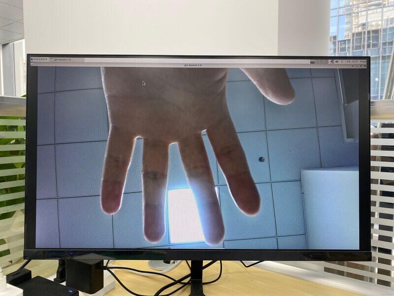
Camera
MIPI-CSI
Use the IMX415 module for the camera. After connecting and powering on the camera module you can view the boot log:
armsom@armsom-sige5:/# dmesg | grep imx415
[    2.547754] imx415 3-001a: driver version: 00.01.08
[    2.547767] imx415 3-001a:  Get hdr mode failed! no hdr default
[    2.547819] imx415 3-001a: Failed to get power-gpios
[    2.547826] imx415 3-001a: could not get default pinstate
[    2.547831] imx415 3-001a: could not get sleep pinstate
[    2.547850] imx415 3-001a: supply dvdd not found, using dummy regulator
[    2.547918] imx415 3-001a: supply dovdd not found, using dummy regulator
[    2.547945] imx415 3-001a: supply avdd not found, using dummy regulator
[    2.613843] imx415 3-001a: Detected imx415 id 0000e0
[    2.613890] rockchip-csi2-dphy csi2-dphy0: dphy0 matches m00_b_imx415 3-001a:bus type 5
[   18.386174] imx415 3-001a: set fmt: cur_mode: 3864x2192, hdr: 0
[   18.389067] imx415 3-001a: set exposure(shr0) 2047 = cur_vts(2250) - val(203)
Use v4l2-ctl for image capture:
// MIPI-CSI1
armsom@armsom-sige5:/# v4l2-ctl -d /dev/video31 --set-fmt-video=width=3840,height=2160,pixelformat=NV12 --stream-mmap=3 --stream-skip=60 --stream-to=/tmp/cif73.out --stream-count=3 --stream-poll

// MIPI-CSI2
armsom@armsom-sige5:/# v4l2-ctl -d /dev/video22 --set-fmt-video=width=3840,height=2160,pixelformat=NV12 --stream-mmap=3 --stream-skip=60 --stream-to=/tmp/cif73.out --stream-count=3 --stream-poll
Record video directly with gst-launch-1.0:
// MIPI-CSI1
armsom@armsom-sige5:/# gst-launch-1.0 v4l2src device=/dev/video31 ! video/x-raw,format=NV12,width=3840,height=2160, framerate=30/1 ! xvimagesink

// MIPI-CSI2
armsom@armsom-sige5:/# gst-launch-1.0 v4l2src device=/dev/video22 ! video/x-raw,format=NV12,width=3840,height=2160, framerate=30/1 ! xvimagesink
MIPI DSI
ArmSoM-sige5 supports a maximum resolution of 4K@120Hz.
Product Certificates
CE / FCC / RoHS
Purchase Samples
ArmSoM Official Website: [Link]
ArmSoM Official AliExpress Store: [Link]
ArmSoM Official Taobao Store: [Link]
For OEM & ODM, please contact: sales@armsom.org