Product Introduction:W3
Let's get to know W3 in 5 minutes.
Overview
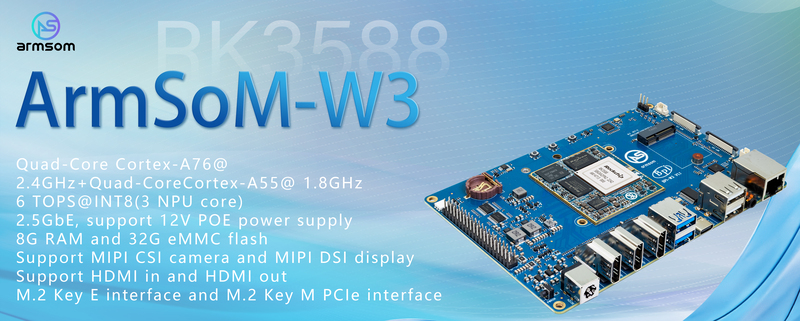
ArmSoM-W3 single board computer is designed and developed by ArmSoM team for professional and enterprise users, powered by Rockchip RK3588 SoC quad ARM Cortex-A76 and quad Cortex-A55 consists of an eight-core CPU processor with dynamic frequency scaling up to 2.4GHz. Embedded high -performance 3D and 2D image acceleration module, AI accelerator NPU with a built -in 6 TOPS computing power.
It supports multiple operating systems.
We can provide baseboard reference design materials for users to customize in-depth independently.
It can be applied to diversified fields such as ARM PCs, edge computing, cloud servers, artificial intelligence, cloud computing, virtual/augmented reality, blockchain, smart NVRs, etc.
Rockchip RK3588 design ArmSoM-Sige7 AI SBC design;
Rockchip RK3588 design ArmSoM-AIM7 Core board fully compatible with Jetson Nano/TX2 NX;
Rockchip RK3588 design ArmSoM-LM7 LGA core board ;
Rockchip RK3588 design ArmSoM-W3 LGA core board maker kit;
With the powerful ecosystem and variety of extension modules, ArmSoM can help users easily go from ideas to prototype to mass production, making it an ideal creative platform for makers, dreamers and hobbyists.
Key Parameters
- SOC: Rockchip RK3588
- CPU: Quad Cortex-A76 @2.4GHz +Quad Cortex-A55 @1.8GHz
- GPU: ARM Mali-G610 MP4
- NPU: 6Tops@INT8
- RAM: 4GB/8GB/16GB(up to 32GB)64-bit LPDDR4/LPDDR4x,Defalut LPDDR4x 8GB
- Flash: 16GB/32GB/64GB/128GB/256GB eMMC, Defaut eMMC 32GB, support MicroSD card extend
- Ethernet: 2.5Gbps Ethernet
- Support 1×HDMI In and 2×HDMI Out
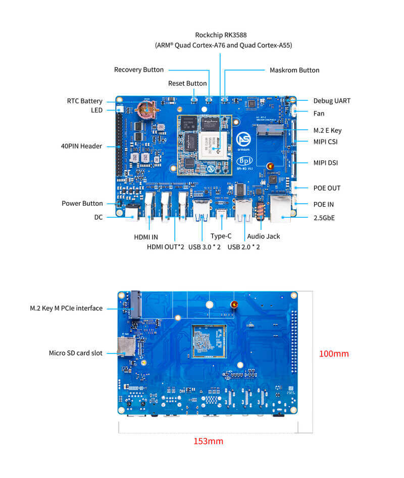
Hardware
Hardware Interface RK3588
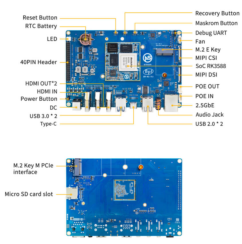
Hardware Interface RK3588M
Hardware Specifications
| Type | Function parameter |
|---|---|
| SOC | |
| CPU | |
| GPU | |
| NPU | |
| VPU/codec | |
| ISP | |
| RAM | |
| Flash | |
| PCIe | |
| Network | |
| Video output | |
| Video input | |
| Audio | |
| USB interface | |
| 40-pin | |
| Others | |
| Power supply | |
| Keys | |
| Operation system | |
| Size | |
| Operating temperature |
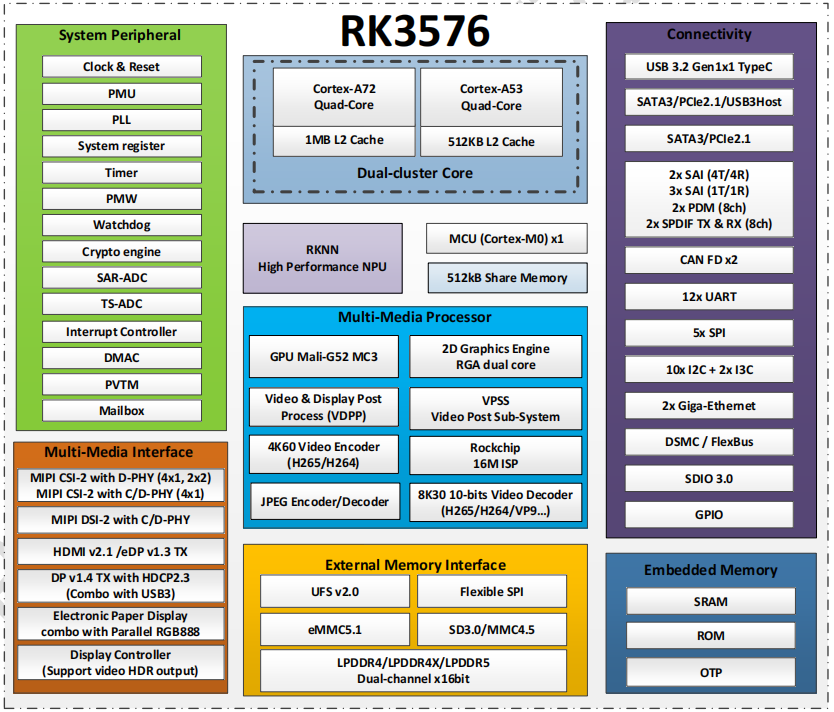
RK3588 Block Diagram
Hardware Pin Definitions
40-pin header
| GPIO number | Function | Pin | Pin | Function | GPIO number |
|---|---|---|---|---|---|
| +3.3V | 1 | 2 | +5.0V | ||
| 139 | I2S1_SDO2_M0 / I2C7_SDA_M3 / UART8_CTSN_M0 / PWM15_IR_M1 / CAN1_TX_M1 / GPIO4_B3 / | 3 | 4 | +5.0V | |
| 138 | I2S1_SDO1_M0 / I2C7_SCL_M3 / UART8_RTSN_M0 / PWM14_M1 / CAN1_RX_M1 / GPIO4_B2 | 5 | 6 | GND | |
| 115 | SPI1_CS1_M1 / I2C8_SDA_M4 / UART7_CTSN_M1 / PWM15_IR_M0 / GPIO3_C3 | 7 | 8 | GPIO0_B5 / UART2_TX_M0 / I2C1_SCL_M0 / I2S1_MCLK_M1 / JTAG_TCK_M2 | 13 |
| GND | 9 | 10 | GPIO0_B6 / UART2_RX_M0 / I2C1_SDA_M0 / I2S1_SCLK_M1 / JTAG_TMS_M2 | 14 | |
| 113 | SPI1_CLK_M1 / UART7_RX_M1 / GPIO3_C1 | 11 | 12 | GPIO3_B5 / CAN1_RX_M0 / PWM12_M0 /UART3_TX_M1 / I2S2_SCLK_M1 | 109 |
| 111 | SPI1_MOSI_M1 / I2C3_SCL_M1 / GPIO3_B7 | 13 | 14 | GND | |
| 112 | SPI1_MISO_M1 / I2C3_SDA_M1 / UART7_TX_M1 / GPIO3_C0 | 15 | 16 | GPIO3_A4 | 100 |
| +3.3V | 17 | 18 | GPIO4_C4 / PWM5_M2 / SPI3_MISO_M0 | 148 | |
| 42 | SPI0_MOSI_M2 / UART4_RX_M2 / GPIO1_B2 | 19 | 20 | GND | |
| 41 | SPI0_MISO_M2 / GPIO1_B1 | 21 | 22 | SARADC_IN4 | |
| 43 | SPI0_CLK_M2 / UART4_TX_M2 / GPIO1_B3 | 23 | 24 | GPIO1_B4 / UART7_RX_M2 /SPI0_CS0_M2 | 44 |
| GND | 25 | 26 | GPIO1_B5 / UART7_TX_M2 / SPI0_CS1_M2 | 45 | |
| 150 | SPI3_CLK_M0 / I2C0_SDA_M1 / PWM7_IR_M3 / GPIO4_C6 | 27 | 28 | GPIO4_C5 / PWM6_M2 / I2C0_SCL_M1 / | |
| 63 | UART1_CTSN_M1 / PWM15_IR_M3 / GPIO1_D7 | 29 | 30 | GND | |
| 47 | SPDIF_TX_M0 / UART1_RX_M1 / PWM13_M2 / GPIO1_B7 | 31 | 32 | GPIO3_C2 / PWM14_M0 / UART7_RTSN_M1 / I2C8_SCL_M4 / SPI1_CS0_M1 | 114 |
| 103 | PWM8_M0 / GPIO3_A7 | 33 | 34 | GND | |
| 110 | I2S2_LRCK_M1 / UART3_RX_M1 / PWM13_M0 / CAN1_TX_M0 / GPIO3_B6 | 35 | 36 | GPIO3_B1 / PWM2_M1 / UART2_TX_M2 | 105 |
| 0 | REFCLK_OUT / GPIO0_A0 | 37 | 38 | GPIO3_B2 /PWM3_IR_M1 / UART2_RX_M2 / I2S2_SDI_M1 | 106 |
| GND | 39 | 40 | GPIO3_B3 / UART2_RTSN / I2S2_SDO_M1 | 107 |
MIPI CSI
0.5mm FPC connector
| Pin | MIPI-CSI | Description |
|---|---|---|
| 1,4,7,10,13,16,19,21,24,25,26,27,32,33 | GND | Power Ground & Signal Ground |
| 2 | MIPI_CSI0_RX_D3N | MIPI RX Lane3 iuput N |
| 3 | MIPI_CSI0_RX_D3P | MIPI RX Lane3 iuput P |
| 5 | MIPI_CSI0_RX_D2N | MIPI RX Lane2 iuput N |
| 6 | MIPI_CSI0_RX_D2P | MIPI RX Lane2 iuput P |
| 8 | MIPI_CSI0_RX_CLK1N | MIPI RX Clock iuput N |
| 9 | MIPI_CSI0_RX_CLK1P | MIPI RX Clock iuput P |
| 11 | MIPI_CSI0_RX_D1N | MIPI RX Lane1 iuput N |
| 12 | MIPI_CSI0_RX_D1P | MIPI RX Lane1 iuput P |
| 14 | MIPI_CSI0_RX_D0N | MIPI RX Lane0 iuput N |
| 15 | MIPI_CSI0_RX_D0P | MIPI RX Lane0 iuput P |
| 17 | MIPI_CSI0_RX_CLK0N | MIPI RX Clock iuput N |
| 18 | MIPI_CSI0_RX_CLK0P | MIPI RX Clock iuput P |
| 20 | MIPI_CAM3_CLKOUT | 1.8V, CLock ouput for Sensor |
| 22 | MIPI_CAM1_CLKOUT | 1.8V, CLock ouput for Sensor |
| 23 | MIPI_CSI0_PDN0_H(GPIO1_B0) | 1.8V, GPIO |
| 24 | I2C3_SCL_M0_MIPI | 1.8V, I2C Clock, pulled up to 1.8V with 2.2K on w3 |
| 25 | I2C3_SDA_M0_MIPI | 1.8V, I2C Clock, pulled up to 1.8V with 2.2K on w3 |
| 26 | MIPI_CSI0_PDN1_H(GPIO1_A7) | 1.8V, GPIO |
| 27 | CM_RST_L(GPIO4_A0) | 3.3V, GPIO |
| 28,29 | VCC_RX | 3.3V Power ouput |
| 30,31 | VCC_5V0 | 5V Power ouput |
MIPI DSI
0.5mm FPC connector (J23)
| Pin | MIPI-DSI | Description |
|---|---|---|
| 1,4,7,10,13,16,27,33,34 | GND | Power and Signal Ground |
| 2 | MIPI_DPHY1_TX_D0N | MIPI1 TX Lane0 ouput N |
| 3 | MIPI_DPHY1_TX_D0P | MIPI1 TX Lane0 ouput P |
| 5 | MIPI_DPHY1_TX_D1N | MIPI1 TX Lane1 ouput N |
| 6 | MIPI_DPHY1_TX_D1P | MIPI1 TX Lane1 ouput P |
| 8 | MIPI_DPHY1_TX_CLKN | MIPI1 TX Clock ouput N |
| 9 | MIPI_DPHY1_TX_CLKP | MIPI1 TX Clock ouput P |
| 11 | MIPI_DPHY1_TX_D2N | MIPI1 TX Lane2 ouput N |
| 12 | MIPI_DPHY1_TX_D2P | MIPI1 TX Lane2 ouput P |
| 14 | MIPI_DPHY1_TX_D3N | MIPI1 TX Lane3 ouput N |
| 15 | MIPI_DPHY1_TX_D3P | MIPI1 TX Lane3 ouput P |
| 17 | LCD_PWM (PWM2_M2/GPIO4_C2) | 1.8V, GPIO/PWM |
| 18,19 | VCC3V3_LCD | 3.3V Power ouput |
| 20 | LCD_RESET (GPIO2_C1) | 1.8V, GPIO |
| 21 | /NC | No Connection |
| 22 | LCD_BL_EN (GPIO3_A1) | 3.3V, GPIO |
| 23 | I2C6_SCL_M0 | 1.8V, I2C Clock, pulled up to 1.8V with 2.2K on w3 |
| 24 | I2C6_SDA_M0 | 1.8V, I2C Data, pulled up to 1.8V with 2.2K on w3 |
| 25 | TP_INT (GPIO0_D3) | 1.8V, GPIO |
| 26 | TP_RST (GPIO0_C6) | 1.8V, GPIO |
| 28,29 | VCC5V0_LCD | 5V Power ouput |
| 31,32 | VCC_1V8 | 1.8V Power ouput |
Debug UART
3.3V level signals, 1500000bps
| Pin | Assignment | Description |
|---|---|---|
| 1 | UART2_RX_M0 | intput |
| 2 | UART2_TX_M0 | output |
| 3 | GND | 0V |
PoE In
1.25mm connector
| Pin | Assignment | Description |
|---|---|---|
| 1 | VC1 | TX1 |
| 2 | VC2 | RX1 |
| 3 | VC3 | TX2 |
| 4 | VC4 | RX2 |
PoE Out
2.0mm connector
| Pin | Assignment | Description |
|---|---|---|
| 1 | VDD_POE | 12V Power ouput |
| 2 | VDD_POE | 12V Power ouput |
| 3 | GND | GND |
| 4 | GND | GND |
Resources
Source Code
Official Images
Based on Debian bullseye works as official operating system by the ArmSom team.
The following systems have been tested and verified by ArmSoM officially:
Download link: Google Drive link
Debian bullseye
Image location: 3. Linux Images/debian/ArmSoM-LM7(Development Kit ArmSoM-W3) - Google Drive link
Android 12
Image location: 4. Android Images/ArmSoM-LM7(Development Kit ArmSoM-W3) - Google Drive link
Release Information
View the initial official release announcement for ArmSoM-W3 here:
System Release Notice for ArmSoM-W3
Third Party Systems
armbian

Armbian_23.11.0-trunk_Armsom-w3_bookworm_legacy_5.10.160.img
Armbian_23.11.0-trunk_Armsom-w3_bookworm_legacy_5.10.160_cinnamon_desktop.img
Armbian_23.11.0-trunk_Armsom-w3_jammy_legacy_5.10.160.img
Armbian_23.11.0-trunk_Armsom-w3_jammy_legacy_5.10.160_xfce_desktop.img
Ubuntu
Image location: 3. Linux Images/ubuntu/ArmSoM-W3 - Google Drive link
joshua-ubuntu-rockchip-download
Hardware Resources
ArmSoM-W3_1V1 Schematics pdf, orcad source - Download schematics pdf and source files (orcad)
ArmSoM-W3_1V1 PCB PADS - Download PCB source files (PADS)
ArmSoM-W3 Top, Bottom - Download 2D CAD files
ArmSoM-W3_1V1 Assembly Drawing - Download components Position Reference of W3 V1.1
User Manual
The user manual for the LM7 development kit (ArmSoM-W3) to help software engineers master the use of the development board.
Getting Started
Before starting to use the ArmSoM-W3, please prepare the following items:
Tool Preparation
- ArmSoM-W3 main board
- Power supply (choose one of three)
- USB Type-C PD 2.0 supporting 9V/2A, 12V/2A, 15V/2A and 20V/2A
- DC 12V adapter, 2.5mm
- PoE 12V
- System installation (choose one of two)
- MicroSD /TF card boot
- MicroSD card/TF card, Class 10 or above, at least 8GB SDHC, and card reader
- Here are some high speed TF cards tested and verified by the ArmSoM team:
- SanDisk 32GB TF (MicroSD) (developer recommended)
- SanDisk 32GB TF (MicroSD) Car Recorder & Security Monitoring Special Storage Card (recommended for long-term operation)
- Sandisk TF 8G Class10 microSD
- Sandisk TF 128G Class10 microSD XC TF 128G 48MB/S
- Onboard eMMC boot
- USB A to C data cable, to write images to the ArmSoM-W3 eMMC or use fastboot/adb commands over the type C port. You need a USB A to type C data cable connecting the ArmSoM-W3 and PC.
- MicroSD /TF card boot
Optional Accessories
- USB keyboard & mouse
- HDMI display and HDMI cable
- The ArmSoM-W3 is equipped with a full-size HDMI port, with maximum support for 8K@60 display.
- HDMI EDID is used to determine the best display resolution. This resolution will be selected on displays and TVs that support 1080p (or 4K/8K). If not for 1080p, EDID will find the next available resolution.
- Ethernet cable
- The ArmSoM-W3 supports ethernet internet access, up to 2.5G.
- The network cable is used to connect the ArmSoM-W3 to the local network and internet.
- Camera module
- The ArmSoM-W3 supports camera capabilities.
- It is recommended to use the imx415 module, available through the ArmSoM Official Taobao store.
- LCD display
- The ArmSoM-W3 supports LCD display capabilities.
- It is recommended to use the ArmSoM Display 10.1 HD, available through the ArmSoM Official Taobao store.
- Audio cable
- Standard 3.5mm jack can be used to play audio via speakers or headphones.
- WiFi/Bluetooth card
- ArmSoM supports common wireless modules on the market, please check the Wireless section of the supported list.
- It is recommended to use RTL8852be, AP6256
- USB-A to USB-C data cable
Image Flashing Options
Interface Settings
For the first time using the ArmSoM-W3 development kit, please first get familiar with the Peripheral Interfaces to better understand the subsequent content.
2.5G Ethernet
If you are using wired ethernet internet, please insert the network cable into the RJ45 port on the ArmSoM-W3, and then the wired connection prompt will pop up on the system desktop.
How to manually configure ethernet?
- Switch to root user
sudo su
- Use the command -ifconfig to check if ethernet is working properly, then showing the eth0 or enP4p65s0 network card and ethernet IP address. Also use the ping tool to test connectivity to the network.
ifconfig
ping www.baidu.com
- If unable to ping, please try:
$ sudo dhclient eth0
or
$ sudo dhclient enP4p65s0
Audio
View the sound cards in the system.
armsom@armsom-w3:/# aplay -l
**** List of PLAYBACK Hardware Devices ****
card 0: rockchipdp0 [rockchip,dp0], device 0: rockchip,dp0 spdif-hifi-0 [rockchip,dp0 spdif-hifi-0]
 Subdevices: 1/1
 Subdevice #0: subdevice #0
card 1: rockchipes8316 [rockchip-es8316], device 0: fe470000.i2s-ES8316 HiFi es8316.7-0011-0 [fe470000.i2s-ES8316 HiFi es8316.7-0011-0]
  Subdevices: 1/1
  Subdevice #0: subdevice #0
card 3: rockchiphdmi0 [rockchip-hdmi0], device 0: rockchip-hdmi0 i2s-hifi-0 [rockchip-hdmi0 i2s-hifi-0]
  Subdevices: 1/1
  Subdevice #0: subdevice #0
card 4: rockchiphdmi1 [rockchip-hdmi1], device 0: rockchip-hdmi1 i2s-hifi-0 [rockchip-hdmi1 i2s-hifi-0]
  Subdevices: 1/1
  Subdevice #0: subdevice #0
USB Interface
The ArmSoM-W3 provides two USB 2.0 and two USB 3.0 ports.
Type-C
The ArmSoM-W3 features a full-featured USB Type‐C 3.0 port which supports up to 8K@30fps DP display.
HDMI
The ArmSoM-W3 has two HDMI output ports, both supporting CEC and HDMI 2.1, with maximum resolutions of 8Kp60 and 4Kp60 respectively.
Note: Please confirm the interface specifications of the HDMI cable before use.
HDMI IN
The ArmSoM-W3 uses the native rk3588 hdmi rx interface.The hdmi in interface can be tested using v4l2 commands.
View all video nodes
ls /dev/video*
Find rk hdmirx device
Execute command v4l2-ctl -d to specify video node. Execute command -D to view node info. Check for rk_hdmirx device using driver name.
armsom@armsom-w3:/# v4l2-ctl -d /dev/video0 -D
Driver Info:
Driver name : rk_hdmirx
Card type : rk_hdmirx
Bus info : fdee0000.hdmirx-controller
Driver version : 5.10.66
Capabilities : 0x84201000
Video Capture Multiplanar
Streaming
Extended Pix Format
Device Capabilities
Device Caps : 0x04201000
Video Capture Multiplanar
Streaming
Extended Pix Format
Query resolution and image formats
Query current resolution and image formats:
armsom@armsom-w3:/# v4l2-ctl -d /dev/video17 --get-fmt-video
Format Video Capture Multiplanar:
Width/Height : 3840/2160
Pixel Format : 'NV16'
Field : None
Number of planes : 1
Flags : premultiplied-alpha, 000000fe
Colorspace : Unknown (1025fcdc)
Transfer Function : Unknown (00000020)
YCbCr Encoding : Unknown (000000ff)
Quantization : Default
Plane 0 :
Bytes per Line : 3840
Size Image : 16588800
Capture image files
Save image files to device and view with 7yuv etc:
v4l2-ctl --verbose -d /dev/video17 \
--set-fmt-video=width=3840,height=2160,pixelformat='NV16' \
--stream-mmap=4 --stream-skip=3 \
--stream-to=/data/4k60_nv16.yuv \
--stream-count=5 --stream-poll
RGB LED
The ArmSoM-W3 has a power LED and user LED.
Power Indicator LED
The power LED is green. On the ArmSoM-W3 it is solid on by default when powered.User Indicator LED
The user LED is blue. By default its blinking state shows a running kernel.
The user can control via commands:
armsom@armsom-w3:/# sudo su
root@armsom-w3:/# echo timer > /sys/class/leds/blue:status/trigger
root@armsom-w3:/# echo activity > /sys/clas
RTC
- The ArmSoM-W3 is equipped with an RTC IC hym8563.
- First, insert the RTC battery to power the RTC IC.
- Note that we should keep the RTC battery in the RTC connector and confirm the rtc hym8563 device has been created
armsom@armsom-w3:/#  dmesg | grep rtc
[    6.407133] rtc-hym8563 6-0051: rtc information is valid
[    6.412731] rtc-hym8563 6-0051: registered as rtc0
[    6.413779] rtc-hym8563 6-0051: setting system clock to 2022-06-22T01:22:26 UTC (1655860946)
- Locating rtc0, then use the following commands to set system time and sync to rtc0.
armsom@armsom-w3:/# hwclock -r
2023-11-03 10:32:40.461910+00:00
armsom@armsom-w3:/# date
11/03/2023 Friday 10:33:12 UTC
armsom@armsom-w3:/# hwclock -w
armsom@armsom-w3:/# hwclock -r
armsom@armsom-w3:/# poweroff
- Removing RTC battery, after 10mins or longer insert battery and boot ArmSoM-W3, check if RTC is in sync with system clock
armsom@armsom-w3:/# hwclock -r
2023-11-03 10:35:40.461910+00:00
armsom@armsom-w3:/# date
11/03/2023 Friday 10:36:01 UTC
Fan
The ArmSoM-W3 is equipped with a 5V fan, using a 1.25mm connector
armsom@armsom-w3:/# echo 0 > /sys/devices/platform/fd8b0010.pwm/pwm/pwmchip*/export
armsom@armsom-w3:/# echo 10000 > /sys/devices/platform/fd8b0010.pwm/pwm/pwmchip*/pwm0/period
armsom@armsom-w3:/# echo 5000 > /sys/devices/platform/fd8b0010.pwm/pwm/pwmchip*/pwm0/duty_cycle
armsom@armsom-w3:/# echo inversed  > /sys/devices/platform/fd8b0010.pwm/pwm/pwmchip*/pwm0/polarity
armsom@armsom-w3:/# echo 1 > /sys/devices/platform/fd8b0010.pwm/pwm/pwmchip*/pwm0/enable
armsom@armsom-w3:/# echo 0 > /sys/devices/platform/fd8b0010.pwm/pwm/pwmchip*/pwm0/enable
M.2 Interface
The ArmSoM-W3 provides two M.2 connectors:
- There is an M.2 E Key connector on the front of the board with a 2230 mounting hole, providing PCIe 2.1 single-channel, USB, SATA, SDIO, PCM and UART signals, supporting standard industrial M.2 WiFi 6 modules.
ArmSoM recommends using RTL8852BE, AP6256. Installed in the ArmSoM-W3 M.2 E slot and then it can get online after wifi setup.
# Load driver
armsom@armsom-w3:/# insmod system/lib/modules/rtkm.ko
armsom@armsom-w3:/# insmod system/lib/modules/rtkm.ko
armsom@armsom-w3:/# insmod /usr/lib/modules/rtk_btusb.ko
armsom@armsom-w3:/# lsmod
Module                  Size  Used by
8852be               4030464  0
rtkm                   16384  1 8852be
rtk_btusb              57344  0
WIFI
# 1. Switch to super user mode
armsom@armsom-w3:/# sudo su
# 2. Open the WIFI
root@armsom-w3:/# nmcli r wifi on
# 3. Scan WIFI
root@armsom-w3:/# nmcli dev wifi
# 4. Connect to WIFI network
root@armsom-w3:/# nmcli dev wifi connect "wifi_name" password "wifi_password"
BT
# 1. Activate bluetooth
armsom@armsom-w3:/# service bluetooth start
# 2. Enter to bluetoothctl
armsom@armsom-w3:/# bluetoothctl
# 3. Input the below commands to connect
armsom@armsom-w3:/# power on
armsom@armsom-w3:/# agent on
armsom@armsom-w3:/# default-agent
armsom@armsom-w3:/# scan on
armsom@armsom-w3:/# pair yourDeviceMAC
- There is an M.2 M Key connector on the back of the ArmSom-W3 with a quad-channel PCIe 3.0 interface. There is a standard M.2 2280 mounting hole on board that can deploy M.2 2280 NVMe SSDs. Note: This M.2 interface does not support M.2 SATA SSDs.
armsom@armsom-w3:/# mkdir temp
armsom@armsom-w3:/# mount /dev/nvme0n1 temp
MIC Recording
armsom@armsom-w3:~# arecord -D hw:1,0 -f S16_LE -t wav -c2 -r 16000 -d 3 t.wav
Recording WAVE 't.wav' : Signed 16 bit Little Endian, Rate 16000 Hz, Stereo
armsom@armsom-w3:~# aplay t.wav
Playing WAVE 't.wav' : Signed 16 bit Little Endian, Rate 16000 Hz, Stereo
Camera
MIPI-CSI
The camera uses the IMX415 module. After connecting and powering on the camera module you can view the boot logs.
armsom@armsom-w3:/# dmesg | grep imx415
[    2.547754] imx415 3-001a: driver version: 00.01.08
[    2.547767] imx415 3-001a:  Get hdr mode failed! no hdr default
[    2.547819] imx415 3-001a: Failed to get power-gpios
[    2.547826] imx415 3-001a: could not get default pinstate
[    2.547831] imx415 3-001a: could not get sleep pinstate
[    2.547850] imx415 3-001a: supply dvdd not found, using dummy regulator
[    2.547918] imx415 3-001a: supply dovdd not found, using dummy regulator
[    2.547945] imx415 3-001a: supply avdd not found, using dummy regulator
[    2.613843] imx415 3-001a: Detected imx415 id 0000e0
[    2.613890] rockchip-csi2-dphy csi2-dphy0: dphy0 matches m00_b_imx415 3-001a:bus type 5
[   18.386174] imx415 3-001a: set fmt: cur_mode: 3864x2192, hdr: 0
[   18.389067] imx415 3-001a: set exposure(shr0) 2047 = cur_vts(2250) - val(203)
Use v4l2-ctl for image capture
armsom@armsom-w3:/# v4l2-ctl -d /dev/video11 --set-fmt-video=width=3840,height=2160,pixelformat=NV12 --stream-mmap=3 --stream-skip=60 --stream-to=/tmp/cif73.out --stream-count=3 --stream-poll
Use gst-launch-1.0 for direct video recording
armsom@armsom-w3:/# gst-launch-1.0 v4l2src device=/dev/video11 ! video/x-raw,format=NV12,width=3840,height=2160, framerate=30/1 ! xvimagesink
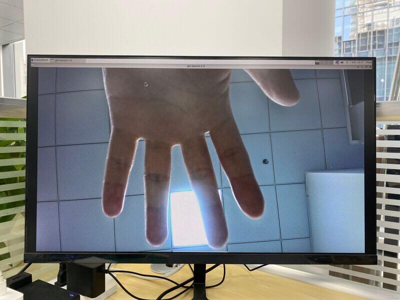
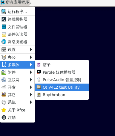
USB3.0 Camera
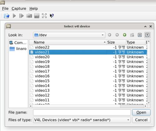
After connecting the usb3.0 camera, open the Qt V4L2 test Utility app for testing
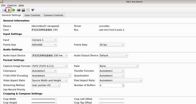
Open video node: video21
Click the camera button and you will see the camera screen
MIPI DSI
The ArmSoM-W3 has a maximum resolution up to 4K@60Hz
Easy to buy sample
ArmSoM online shop: https://www.armsom.org/product-page/sige7
ArmSoM Aliexpress online shop: https://www.aliexpress.com/item/3256805434864544.html
ArmSoM Taobao shop: https://item.taobao.com/item.htm?id=714794342755
OEM&ODM, please contact: sales@armsom.org