Product Introduction:Sige7
Let's get to know Sige7 in 5 minutes.
Overview
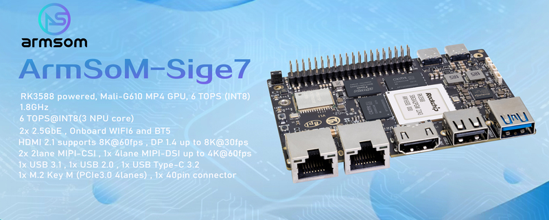
The ArmSoM-Sige7 is powered by Rockchip's latest flagship RK3588,octa-core 64-bit processor, with a max frequency of 2.4GHz, a 6 TOPS NPU, and up to 32GB of RAM.
Rockchip RK3588 design ArmSoM-Sige7 AI SBC design;
Rockchip RK3588 design ArmSoM-AIM7 Core board fully compatible with Jetson Nano/TX2 NX;
Rockchip RK3588 design ArmSoM-LM7 LGA core board ;
Rockchip RK3588 design ArmSoM-W3 LGA core board maker kit;
With the powerful ecosystem and variety of extension modules, ArmSoM can help users easily go from ideas to prototype to mass production, making it an ideal creative platform for makers, dreamers and hobbyists.
Sige 7 is applied for various applications,such as, ARM PCs, edge computing, cloud servers, AI, cloud computing, virtual/augmented reality, blockchain, smart NVRs and more.
Key Parameter
- SoC: Rockchip RK3588
- CPU: 4x Cortex-A76 @ 2.4GHz + 4x Cortex-A55 @ 1.8GHz, 8nm
- GPU: ARM Mali-G610 MP4
- NPU: Up to 6 TOPS (INT8), supports INT4/INT8/INT16 mixed computing
- VPU/Codec:
- Hardware Decode: 8K@60fps H.265/VP9/AVS2, 8K@30fps H.264 AVC/MVC, 4K@60fps AV1, 1080P@60fps MPEG-2/-1/VC-1/VP8
- Hardware Encode: 8K@30fps H.265 / H.264
- RAM: 8GB/16GB/32GB (max 32GB) 64bit LPDDR4/LPDDR4x, default 8GB LPDDR4x
- Storage: 64GB/128GB eMMC, default 64GB eMMC
- Operating Voltage: Wide input voltage, 5V to 20V (±5% tolerance)
- Operating temperature: 0°C ~ 80°C
- OS:
- Official: Android 12.0, Debian 11, Buildroot
- 3rd party: Armbian, Ubuntu 20.04, Ubuntu 22.04, Kylin OS
- PCB: 12-layer
- Weight: 46.6g
- Size: 92mm × 62mm
Hardware
Hardware Interface
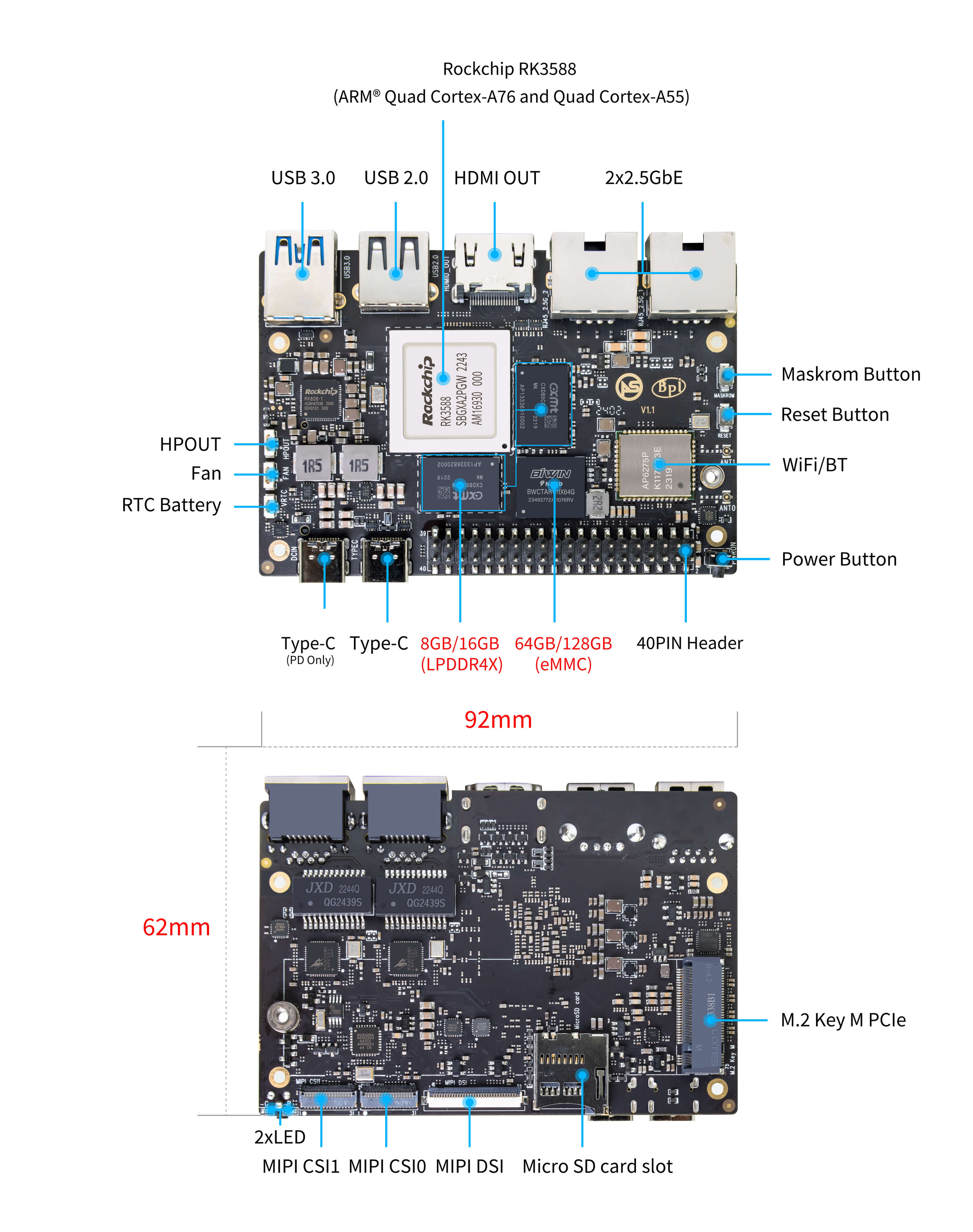
There are two identical Type-C ports on Sige7,but only the Type-C (PD Only) port is for power input.
Hardware Spec
| Category | Functional Parameters |
|---|---|
| SOC | |
| CPU | |
| GPU | |
| NPU | |
| VPU/Codec | |
| ISP | |
| RAM | |
| Flash | |
| PCIe | |
| Networking | |
| Video Out | |
| Video In | |
| Audio | |
| USB | |
| 40-pin | |
| Other | |
| Power Input | |
| Buttons | |
| OS Support | |
| Dimensions | |
| Operating temperature |
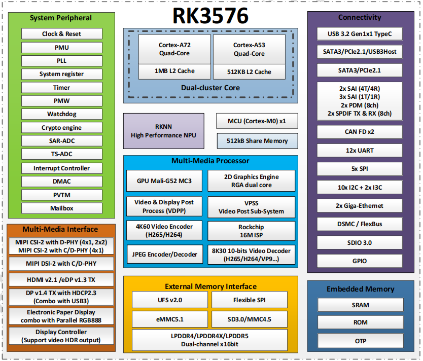
RK3588 Block Diagram
Hardware Pin Definitions
40-pin header
| GPIO number | Function | Pin | Pin | Function | GPIO number |
|---|---|---|---|---|---|
| +3.3V | 1 | 2 | +5.0V | ||
| 139 | I2S1_SDO2_M0 / I2C7_SDA_M3 / UART8_CTSN_M0 / PWM15_IR_M1 / CAN1_TX_M1 / GPIO4_B3 / | 3 | 4 | +5.0V | |
| 138 | I2S1_SDO1_M0 / I2C7_SCL_M3 / UART8_RTSN_M0 / PWM14_M1 / CAN1_RX_M1 / GPIO4_B2 | 5 | 6 | GND | |
| 115 | SPI1_CS1_M1 / I2C8_SDA_M4 / UART7_CTSN_M1 / PWM15_IR_M0 / GPIO3_C3 | 7 | 8 | GPIO0_B5 / UART2_TX_M0 / I2C1_SCL_M0 / I2S1_MCLK_M1 / JTAG_TCK_M2 | 13 |
| GND | 9 | 10 | GPIO0_B6 / UART2_RX_M0 / I2C1_SDA_M0 / I2S1_SCLK_M1 / JTAG_TMS_M2 | 14 | |
| 113 | SPI1_CLK_M1 / UART7_RX_M1 / GPIO3_C1 | 11 | 12 | GPIO3_B5 / CAN1_RX_M0 / PWM12_M0 /UART3_TX_M1 / I2S2_SCLK_M1 | 109 |
| 111 | SPI1_MOSI_M1 / I2C3_SCL_M1 / GPIO3_B7 | 13 | 14 | GND | |
| 112 | SPI1_MISO_M1 / I2C3_SDA_M1 / UART7_TX_M1 / GPIO3_C0 | 15 | 16 | GPIO3_A4 / SPI4_CS1_M1 / I2S3_SDI / UART8_RTSN_M1 | 100 |
| +3.3V | 17 | 18 | GPIO4_C4 / PWM5_M2 / SPI3_MISO_M0 | 148 | |
| 42 | SPI0_MOSI_M2 / UART4_RX_M2 / GPIO1_B2 | 19 | 20 | GND | |
| 41 | SPI0_MISO_M2 / GPIO1_B1 | 21 | 22 | SARADC_IN4 | |
| 43 | SPI0_CLK_M2 / UART4_TX_M2 / GPIO1_B3 | 23 | 24 | GPIO1_B4 / UART7_RX_M2 /SPI0_CS0_M2 | 44 |
| GND | 25 | 26 | GPIO1_B5 / UART7_TX_M2 / SPI0_CS1_M2 | 45 | |
| 150 | SPI3_CLK_M0 / I2C0_SDA_M1 / PWM7_IR_M3 / GPIO4_C6 | 27 | 28 | GPIO4_C5 / PWM6_M2 / I2C0_SCL_M1 / | |
| 63 | UART1_CTSN_M1 / PWM15_IR_M3 / GPIO1_D7 | 29 | 30 | GND | |
| 47 | SPDIF_TX_M0 / UART1_RX_M1 / PWM13_M2 / GPIO1_B7 | 31 | 32 | GPIO3_C2 / PWM14_M0 / UART7_RTSN_M1 / I2C8_SCL_M4 / SPI1_CS0_M1 | 114 |
| 103 | PWM8_M0 / GPIO3_A7 | 33 | 34 | GND | |
| 110 | I2S2_LRCK_M1 / UART3_RX_M1 / PWM13_M0 / CAN1_TX_M0 / GPIO3_B6 | 35 | 36 | GPIO3_B1 / PWM2_M1 / UART2_TX_M2 | 105 |
| 0 | REFCLK_OUT / GPIO0_A0 | 37 | 38 | GPIO3_B2 /PWM3_IR_M1 / UART2_RX_M2 / I2S2_SDI_M1 | 106 |
| GND | 39 | 40 | GPIO3_B3 / UART2_RTSN / I2S2_SDO_M1 | 107 |
MIPI CSI0
0.5mm FPC connector
| Pin | MIPI-CSI | Description |
|---|---|---|
| 1,4,7,10,13,16,24,25,26,27,32,33 | GND | Power Ground & Signal Ground |
| 2 | MIPI_CSI0_RX_D3N | MIPI RX Lane3 iuput N |
| 3 | MIPI_CSI0_RX_D3P | MIPI RX Lane3 iuput P |
| 5 | MIPI_CSI0_RX_D2N | MIPI RX Lane2 iuput N |
| 6 | MIPI_CSI0_RX_D2P | MIPI RX Lane2 iuput P |
| 8 | MIPI_CSI0_RX_CLK1N | MIPI RX Clock iuput N |
| 9 | MIPI_CSI0_RX_CLK1P | MIPI RX Clock iuput P |
| 11 | MIPI_CSI0_RX_D1N | MIPI RX Lane1 iuput N |
| 12 | MIPI_CSI0_RX_D1P | MIPI RX Lane1 iuput P |
| 14 | MIPI_CSI0_RX_D0N | MIPI RX Lane0 iuput N |
| 15 | MIPI_CSI0_RX_D0P | MIPI RX Lane0 iuput P |
| 17 | MIPI_CSI0_RX_CLK0N | MIPI RX Clock iuput N |
| 18 | MIPI_CSI0_RX_CLK0P | MIPI RX Clock iuput P |
| 19 | MIPI_VSYNC | |
| 20 | MIPI_CAM3_CLKOUT | 1.8V, CLock ouput for Sensor |
| 21 | MIPI_HSYNC | |
| 22 | MIPI_CAM1_CLKOUT | 1.8V, CLock ouput for Sensor |
| 23 | MIPI_CSI0_PDN0_H(GPIO1_B0) | 1.8V, GPIO |
| 24 | I2C3_SCL_M0_MIPI | 1.8V, I2C Clock, pulled up to 1.8V with 2.2K on Sige7 |
| 25 | I2C3_SDA_M0_MIPI | 1.8V, I2C Clock, pulled up to 1.8V with 2.2K on Sige7 |
| 26 | MIPI_CSI0_PDN1_H(GPIO1_A7) | 1.8V, GPIO |
| 27 | CM_RST_L(GPIO4_A0) | 3.3V, GPIO |
| 28,29 | VCC_RX | 3.3V Power ouput |
| 30,31 | VCC_5V0 | 5V Power ouput |
MIPI CSI1
0.5mm FPC connector
| Pin | MIPI-CSI | Description |
|---|---|---|
| 1,4,7,10,13,16,24,25,26,27,32,33 | GND | Power Ground & Signal Ground |
| 2 | MIPI_CSI1_RX_D3N | MIPI RX Lane3 iuput N |
| 3 | MIPI_CSI1_RX_D3P | MIPI RX Lane3 iuput P |
| 5 | MIPI_CSI1_RX_D2N | MIPI RX Lane2 iuput N |
| 6 | MIPI_CSI1_RX_D2P | MIPI RX Lane2 iuput P |
| 8 | MIPI_CSI1_RX_CLK1N | MIPI RX Clock iuput N |
| 9 | MIPI_CSI1_RX_CLK1P | MIPI RX Clock iuput P |
| 11 | MIPI_CSI1_RX_D1N | MIPI RX Lane1 iuput N |
| 12 | MIPI_CSI1_RX_D1P | MIPI RX Lane1 iuput P |
| 14 | MIPI_CSI1_RX_D0N | MIPI RX Lane0 iuput N |
| 15 | MIPI_CSI1_RX_D0P | MIPI RX Lane0 iuput P |
| 17 | MIPI_CSI1_RX_CLK0N | MIPI RX Clock iuput N |
| 18 | MIPI_CSI1_RX_CLK0P | MIPI RX Clock iuput P |
| 19 | MIPI_VSYNC | |
| 20 | MIPI_CAM3_CLKOUT / GPIO1_B7 | 1.8V, CLock ouput for Sensor / GPIO |
| 21 | MIPI_HSYNC | |
| 22 | MIPI_CAM0_CLKOUT | 1.8V, CLock ouput for Sensor |
| 23 | MIPI_CSI1_PDN0_H(GPIO1_B0) | 1.8V, GPIO |
| 24 | I2C3_SCL_M0_MIPI | 1.8V, I2C Clock, pulled up to 1.8V with 2.2K on Sige7 |
| 25 | I2C3_SDA_M0_MIPI | 1.8V, I2C Clock, pulled up to 1.8V with 2.2K on Sige7 |
| 26 | MIPI_CSI0_PDN1_H(GPIO1_A7) | 1.8V, GPIO |
| 27 | CM2_RST_L(GPIO4_A0) | 3.3V, GPIO |
| 28,29 | VCC_RX | 3.3V Power ouput |
| 30,31 | VCC_5V0 | 5V Power ouput |
MIPI DSI
0.5mm FPC connector (J23)
| Pin | MIPI-DSI | Description |
|---|---|---|
| 1,4,7,10,13,16,27,33,34 | GND | Power and Signal Ground |
| 2 | MIPI_DPHY1_TX_D0N | MIPI1 TX Lane0 ouput N |
| 3 | MIPI_DPHY1_TX_D0P | MIPI1 TX Lane0 ouput P |
| 5 | MIPI_DPHY1_TX_D1N | MIPI1 TX Lane1 ouput N |
| 6 | MIPI_DPHY1_TX_D1P | MIPI1 TX Lane1 ouput P |
| 8 | MIPI_DPHY1_TX_CLKN | MIPI1 TX Clock ouput N |
| 9 | MIPI_DPHY1_TX_CLKP | MIPI1 TX Clock ouput P |
| 11 | MIPI_DPHY1_TX_D2N | MIPI1 TX Lane2 ouput N |
| 12 | MIPI_DPHY1_TX_D2P | MIPI1 TX Lane2 ouput P |
| 14 | MIPI_DPHY1_TX_D3N | MIPI1 TX Lane3 ouput N |
| 15 | MIPI_DPHY1_TX_D3P | MIPI1 TX Lane3 ouput P |
| 17 | LCD_PWM (PWM2_M2/GPIO4_C2) | 1.8V, GPIO/PWM |
| 18,19 | VCC3V3_LCD | 3.3V Power ouput |
| 20 | LCD_RESET (GPIO2_C1) | 1.8V, GPIO |
| 21 | /NC | No Connection |
| 22 | LCD_BL_EN (GPIO3_A1) | 3.3V, GPIO |
| 23 | I2C6_SCL_M0 | 1.8V, I2C Clock, pulled up to 1.8V with 2.2K on Sige7 |
| 24 | I2C6_SDA_M0 | 1.8V, I2C Data, pulled up to 1.8V with 2.2K on Sige7 |
| 25 | TP_INT (GPIO0_D3) | 1.8V, GPIO |
| 26 | TP_RST (GPIO0_C6) | 1.8V, GPIO |
| 28,29 | VCC5V0_LCD | 5V Power ouput |
| 31,32 | VCC_1V8 | 1.8V Power ouput |
Fan
0.8mm connector(CN32)
| Pin | Assignment | Description |
|---|---|---|
| 1 | VCC_5V0 | 5V Power ouput |
| 2 | GND | GND |
| 3 | PWM | PWM control |
Resources
Source Code
ArmSoM github source code : https://github.com/ArmSoM/armsom-build
ArmSoM-Sige7 kernel: https://github.com/ArmSoM/ubuntu-linux-rockchip
ArmSoM-Sige7 uboot: https://github.com/ArmSoM/u-boot
openwrt(istoreos): https://github.com/istoreos/istoreos
RKNN-LLM: RKNN-LLM
Official Image
ArmSoM team uses Debian bullseye as the official operating system.
Download
The following systems have been tested and verified by ArmSoM official:
Network disk address: Google Drive link
debain bullseye
Firmware location: 3. Linux image/debian/ArmSoM-Sige7 - Google Drive link
Third Party System
Ubuntu
Image location: 3. Linux Images/ubuntu/ArmSoM-Sige7 - Google Drive link
joshua-ubuntu-rockchip-download
istoreos
Firmware location: 3. Linux image/openwrt/ArmSoM-Sige7 - Google Drive link
armbian

Firmware location: 3. Linux image/armbian/ArmSoM-Sige7 - Google Drive link
jammy_edge_6.8.2_gnome_desktop: armbian-releases
bookworm_edge_6.8.2_minimal: armbian-releases
jammy_6.1.43_gnome: armbian-releases
bookworm_6.1.43_minimal: armbian-releases
Hardware Resources
- ArmSoM-Sige7_1V1 Schematics pdf - Schematics pdf
V1.1
- VOL_IC: U27/U7/U6301change part pin;
- USB:U15 fr o m TypeC1 change t o TypeC0; CN31 fr o m USB3. 0 change t o USB2. 0;
- 40PIN:add UART Pr ot ect; J 2&CN2&CN32 change t o WF0. 8;
- CAM:DEL R6352, CSI _1 I2C3 change t o I2C4;
- WIFI Module: AP6275S change to AP6275P;
ArmSoM-Sige7_1V1 Top, Bottom - Download 2D CAD files
ArmSoM-Sige7_1V1 SMD - Download components Position Reference of Sige7 V1.1
ArmSoM-Sige7 datasheet - datasheet
User Manual
The Sige7 user manual helps users understand the basic usage and preparation work needed for Sige7.
Its model and hardware version can be found printed on the board when you got Sige 7.
This article gives an overview of the product information to you in as much detail as possible.
Getting Started
Before starting to use the ArmSoM-Sige7, please prepare the following items:
Tool Preparation
- Sige7 main board
- Power supply: USB Type-C PD
- Support 9V/2A, 12V/2A, 15V/2A
- System installation (choose one)
- MicroSD /TF card boot
- MicroSD card/TF, Class 10 or above, at least 8GB SDHC and a card reader
- High speed TF cards tested by the ArmSoM team:
- SanDisk 32GB TF (MicroSD) (developer recommended)
- SanDisk 32GB TF (MicroSD) Dashcam & Security Camera Storage Card (recommended for long-term operation)
- Sandisk TF 8G Class10 microSD
- Sandisk TF 128G Class10 microSD XC TF 128G 48MB/S:
- Onboard eMMC boot
- USB Type-C data cable to write image from Type-C port on Sige7 to eMMC. You need to connect Sige7 to a PC using the Type-C cable.
- MicroSD /TF card boot
Optional Accessories
- USB keyboard and mouse
- HDMI display and HDMI cable
- Sige7 features a full-sized HDMI port, and supports up to 8K@60 display
- HDMI EDID is used to determine optimum display resolution. 1080p (or 4K/8K) will be selected on displays and TVs that support it. If 1080p is not supported, EDID will find the next available resolution.
- Ethernet cable
- Sige7 supports 2.5Gb Ethernet
- The network cable is used to connect Sige7 to a local network and the Internet
- Camera module
- Sige7 supports camera function
- We recommend using the imx415 module, available through the ArmSoM Taobao store or AliExpress or email to sales@armsom.org
- LCD display
- Sige7 supports LCD display
- We recommend the ArmSoM Display 10.1 HD, available through the ArmSoM Taobao store or AliExpress or email to sales@armsom.org
- Audio cable
- Available for 0.8mm vertical socket
- USB-A to USB-C data cable
Image Flashing
Interface Setup
If this is your first time using the ArmSoM-Sige7, please familiarize yourself with the [Peripheral Interfaces](#Hardware Interface) to better understand the content below.
Debug Serial Port
Connect the USB to TTL serial cable as follows:
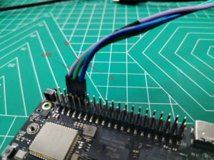
| sige5 | Connect | Serial Module |
|---|---|---|
| GND (pin 6) | <---> | GND |
| TX (pin 8) | <---> | RX |
| RX (pin 10) | <---> | TX |
2.5G Ethernet
If using wired Ethernet, insert the network cable into the RJ45 port on the ArmSoM-Sige7 and the wired connection will pop up on the desktop.
- Use the
ifconfigcommand to check if Ethernet is working normally - it will display the NIC enP2p33s0 or enP4p65s0 and Ethernet IP address. Also use thepingtool to test network connectivity.
ifconfig
ping mi.com
- If unable to ping,please try:
$ sudo dhclient enP2p33s0
or
$ sudo dhclient enP4p65s0
HDMI
The ArmSoM-Sige7 has an HDMI output port which supports CEC and HDMI 2.1, maximum resolution up to 8Kp60.
USB
The ArmSoM-Sige7 provides one USB 2.0 and one USB 3.0 port.
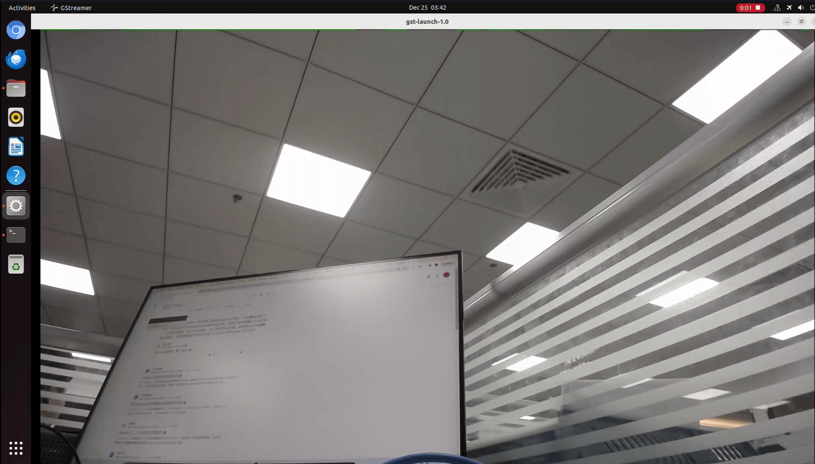
USB3.0 Camera
After connecting a USB 3.0 camera, you can download cheese and use the camera with the following commands:
armsom@armsom-sige7: sudo apt update
armsom@armsom-sige7: sudo apt install cheese
You can also preview the camera in the terminal:
gst-launch-1.0 v4l2src device=/dev/video0 io-mode=4 ! videoconvert ! video/x-raw,format=NV12,width=1920,height=1080 ! xvimagesink;
Take Photo:
gst-launch-1.0 v4l2src device=/dev/video0 io-mode=4 ! videoconvert ! video/x-raw,format=NV12,width=1920,height=1080 ! jpegenc ! multifilesink location=/home/armsom/test.jpg;
Record video:
gst-launch-1.0 v4l2src num-buffers=512 device=/dev/video0 io-mode=4 ! videoconvert ! video/x-raw, format=NV12, width=1920, height=1080, framerate=30/1 ! tee name=t ! queue ! mpph264enc ! queue ! h264parse ! mpegtsmux ! filesink location=/home/armsom/test.mp4
Audio
View sound cards in the system:
armsom@armsom-sige7:/# aplay -l
**** List of PLAYBACK Hardware Devices ****
card 0: rockchipdp0 [rockchip,dp0], device 0: rockchip,dp0 spdif-hifi-0 [rockchip,dp0 spdif-hifi-0]
 Subdevices: 1/1
 Subdevice #0: subdevice #0
card 1: rockchipes8316 [rockchip-es8316], device 0: fe470000.i2s-ES8316 HiFi es8316.7-0011-0 [fe470000.i2s-ES8316 HiFi es8316.7-0011-0]
  Subdevices: 1/1
  Subdevice #0: subdevice #0
card 2: rockchiphdmi0 [rockchip-hdmi0], device 0: rockchip-hdmi0 i2s-hifi-0 [rockchip-hdmi0 i2s-hifi-0]
  Subdevices: 1/1
  Subdevice #0: subdevice #0
Fan
The Sige7 features a 5V fan using a 0.8mm connector
armsom@armsom-sige7:/# echo 100 > /sys/devices/platform/pwm-fan/hwmon/hwmon8/pwm1
Type-C
The Sige7 features a full-featured USB Type‐C 3.0 port which supports up to 8K@30fps DP display.
40Pin
The Sige7 provides a 40-pin GPIO header, compatible with most sensors on the market.
RGB LED
The Sige7 has two user LEDs - green and red.
User Green LED
Constantly indicates running kernel by default.User Red LED Off by default, can be controlled by user.
Users can control with commands:
armsom@armsom-sige7:/# sudo su
armsom@armsom-sige7:/# echo timer > /sys/class/leds/red/trigger
armsom@armsom-sige7:/# echo activity > /sys/class/leds/red/trigger
RTC
- The Sige7 features an hym8563 RTC chip.
- First, insert the RTC battery using the 2-pin header to supply power to the RTC IC.
- Note that we should keep the RTC battery in the RTC connector and confirm the rtc hym8563 device which has been created.
armsom@armsom-sige7:/# dmesg | grep rtc
[ 6.407133] rtc-hym8563 6-0051: rtc information is valid
[ 6.412731] rtc-hym8563 6-0051: registered as rtc0
[ 6.413779] rtc-hym8563 6-0051: setting system clock to 2022-06-22T01:22:26 UTC (1655860946)
- Find rtc0, then use the following commands to set system time and sync to rtc0:
armsom@armsom-sige7:/# hwclock -r
2023-11-03 10:32:40.461910+00:00
armsom@armsom-sige7:/# date
Fri 3rd Nov 10:33:12 UTC 2023
armsom@armsom-sige7:/# hwclock -w
armsom@armsom-sige7:/# hwclock -r
armsom@armsom-sige7:/# poweroff
- Turn off the RTC battery for 10+ minutes, insert the battery again and boot Sige7, and check if RTC synced with system clock:
armsom@armsom-sige7:/# hwclock -r
2023-11-03 10:35:40.461910+00:00
armsom@armsom-sige7:/# date
Fri 3rd Nov 10:36:01 UTC 2023
M.2
The ArmSoM-Sige7 provides an M.2 connector:
- There is an M.2 M Key connector on the back with a 4-lane PCIe 3.0 interface. The board has a standard M.2 2280 mounting hole to deploy M.2 2280 NVMe SSDs.
Note: This M.2 interface does NOT support M.2 SATA SSDs.
armsom@armsom-sige7:/# mkdir temp
armsom@armsom-sige7:/# mount /dev/nvme0n1 temp
Camera
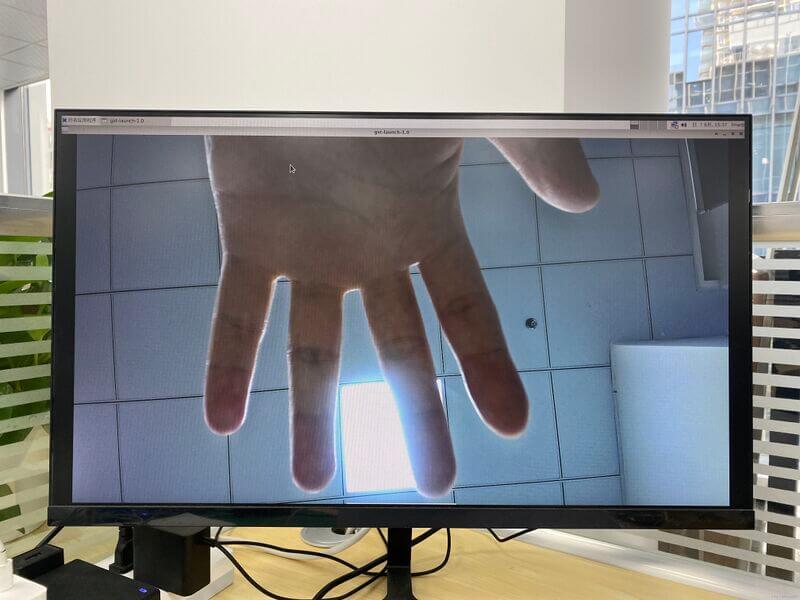
MIPI-CSI
Use the IMX415 module for the camera. After connecting and powering on the camera module you can view the boot log:
armsom@armsom-sige7:/# dmesg | grep imx415
[ 2.547754] imx415 3-001a: driver version: 00.01.08
[ 2.547767] imx415 3-001a: Get hdr mode failed! no hdr default
[ 2.547819] imx415 3-001a: Failed to get power-gpios
[ 2.547826] imx415 3-001a: could not get default pinstate
[ 2.547831] imx415 3-001a: could not get sleep pinstate
[ 2.547850] imx415 3-001a: supply dvdd not found, using dummy regulator
[ 2.547918] imx415 3-001a: supply dovdd not found, using dummy regulator
[ 2.547945] imx415 3-001a: supply avdd not found, using dummy regulator
[ 2.613843] imx415 3-001a: Detected imx415 id 0000e0
[ 2.613890] rockchip-csi2-dphy csi2-dphy0: dphy0 matches m00_b_imx415 3-001a:bus type 5
[ 18.386174] imx415 3-001a: set fmt: cur_mode: 3864x2192, hdr: 0
[ 18.389067] imx415 3-001a: set exposure(shr0) 2047 = cur_vts(2250) - val(203)
Use v4l2-ctl for image capture:
// MIPI-CSI1
armsom@armsom-sige7:/# v4l2-ctl -d /dev/video31 --set-fmt-video=width=3840,height=2160,pixelformat=NV12 --stream-mmap=3 --stream-skip=60 --stream-to=/tmp/cif73.out --stream-count=3 --stream-poll

// MIPI-CSI2
armsom@armsom-sige7:/# v4l2-ctl -d /dev/video22 --set-fmt-video=width=3840,height=2160,pixelformat=NV12 --stream-mmap=3 --stream-skip=60 --stream-to=/tmp/cif73.out --stream-count=3 --stream-poll
Record video directly with gst-launch-1.0:
// MIPI-CSI1
armsom@armsom-sige7:/# gst-launch-1.0 v4l2src device=/dev/video31 ! video/x-raw,format=NV12,width=3840,height=2160, framerate=30/1 ! xvimagesink

// MIPI-CSI2
armsom@armsom-sige7:/# gst-launch-1.0 v4l2src device=/dev/video22 ! video/x-raw,format=NV12,width=3840,height=2160, framerate=30/1 ! xvimagesink
MIPI DSI
The ArmSoM-Sige7 supports up to 4K@60Hz resolution over MIPI DSI
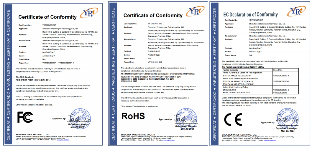
Product Certificate
CE / FC / RoHS
Easy to buy sample
ArmSoM online shop: https://www.armsom.org/product-page/sige7
ArmSoM Aliexpress online shop: https://www.aliexpress.com/store/1102800175
ArmSoM Taobao shop: https://item.taobao.com/item.htm?id=757023687970
OEM&ODM, please contact: sales@armsom.org