12. Screen&Touch Usage
12.1 Mipi Screen
ArmSoM products with MIPI-DSI support adaptation to the [ArmSoM Display 10 HD] module
Connect the wiring according to the following diagram
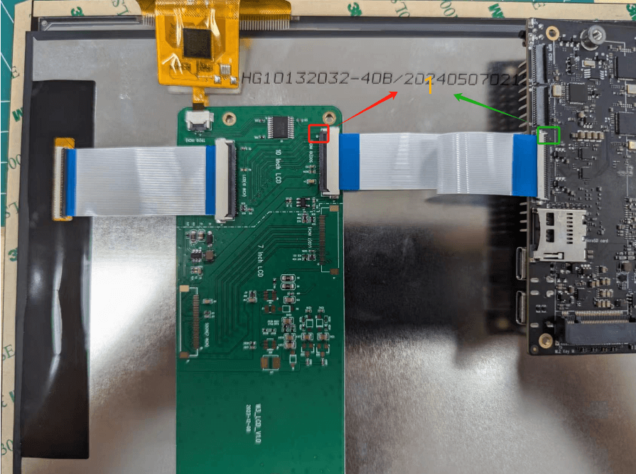
The MIPI-DSI interface does not support hot swapping operations. Do not connect or disconnect the display screen while the system is powered on. Connecting or disconnecting during power on may cause a short circuit in the circuit, which can trigger the protection mechanism of the board to automatically shut down. In severe cases, it may damage the chip interface or burn out the chip.
12.1.2 Enable MIPI-DSI communication interface
The MIPI-CSI interface is turned off by default and needs to be enabled to be used
In the Armbian operating system/ The boot/armbianEnv. txt file is used to configure system startup parameters and device tree plugins.
If you wish to check or enable MIPI-DSI related device tree plugins, you can follow these steps:
-* * View device tree plugin configuration**
Open the file: Open the/boot/armbianEnv. txt file through a terminal and use a text editor such as Nano or Vim, for example:
root@armsom-sige5 :/ home/armsom# sudo nano /boot/armbianEnv.txt
Taking the activation of armsom sige5-display-10hd as an example, open armsom sige5-display-10hd as follows:
//Choose based on the product you have on hand
overlays=armsom-sige7-display-10hd // Sige7
overlays=armsom-sige5-display-10hd // Sige5
overlays=armsom-sige3-display-10hd // Sige3
The 'overlays' line specifies the Device Tree Overlay. If these contents are not available, you can manually add them.
After editing, save the file and exit the editor to restart the system for the configuration to take effect:
//Execute sync first
root@armsom-sige5 :/ home/armsom# sync
root@armsom-sige5 :/ home/armsom# sudo reboot
-Verify if ArmSoM Display 10 HD is enabled**
After enabling the armsom-sige5-display-10hd device tree plugin, restart the board to view the mipi DSI screen displaying the system screen/terminal logs
-Q1: If the power is directly unplugged and restarted, may it result in unmodified files or overlay system startup failure? -A1: When directly unplugging or forcibly shutting down, there may be a situation where files are not synchronized from memory (RAM) to storage devices (such as hard drives, SSDs) in a timely manner. This is because operating systems typically temporarily store data in memory and periodically write this data to disk. To avoid this issue, it is recommended to execute the 'sync' command before shutting down to ensure that all data has been written to the disk, and then unplug or shut down.
12.2 HDMI
HDMI is turned on by default
| Model | Sige7 | Sige5 | Sige3 | Sige1 | LM7 (w3) | CM5 |
|---|---|---|---|---|---|---|
| Resolution | 8Kp60 | 4Kp120 | 4Kp60 | 4Kp60 | 8Kp60 | 4Kp120 |
- Connect ArmSoM products and HDMI monitors using HDMI cables
- If the HDMI monitor has image output after starting the Linux system, it indicates that the HDMI interface is working properly
Note that many laptops come with an HDMI interface, but the HDMI interface of the laptop generally only has an output function and does not have the HDMI in function, which means that it cannot display the HDMI output of other devices on the laptop screen. When you want to connect the HDMI of the development board to the HDMI interface of your laptop, please first confirm that your laptop supports the HDMI in function. When HDMI is not displaying, please first check if the system you are using has a desktop version. If it is a server version, only the terminal can be seen
12.2.1 HDMI to VGA Display Test
The following accessories need to be prepared -HDMI to VGA converter -One VGA cable, supporting VGA interface display
HDMI to VGA display test is as follows
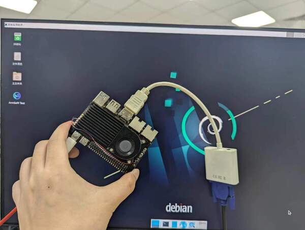
When using HDMI to VGA display, ArmSoM Sige products and Linux systems do not require any settings, as long as the HDMI interface of the development board can display normally. So if there are any issues during testing, please check if there are any problems with the HDMI to VGA converter, VGA cable, and monitor.
12.3 typec (DP display)
DP is open by default
| Model | Sige7 | Sige5 | Sige3 | Sige1 | LM7 (w3) | CM5 |
|---|---|---|---|---|---|---|
| Resolution | 8Kp60 | 4Kp120 | 4Kp60 | 4Kp60 | 8Kp60 | 4Kp120 |
- Connect ArmSoM products and typec displays using a typec cable
- If there is image output from the TypeC monitor after starting the Linux system, it indicates that the TypeC interface is working properly
Note that the ArmSoM product's TypeC output function is 5V/2A. TypeC displays beyond this range are recommended to use external power supply. If the DP interface of the display device requires an external power supply, you need to find a suitable power adapter. Usually, the instruction manual of a display device specifies the specifications of the required power supply, such as voltage, current, and other parameters. Ensure to use a power adapter that meets the requirements to avoid damaging the device.
12.4 Screen Debugging Methods
12.4.1 Mipi Screen
When debugging MIPI screens, it is generally necessary to pay special attention to the screen's power on initialization sequence (panel in sequence) and power off initialization sequence (panel exit sequence).
Preparation work
When obtaining a new MIPI screen, screen manufacturers usually provide two important documents: * screen specification sheet and screen initialization sequence *. These documents are key materials for debugging and configuring screens. The following uses the ArmSoM Display 10 HD screen as an example to illustrate how to use these materials.
-Screen Specification Book: In the screen specification book, you can find detailed parameters about the screen, such as resolution, color depth, interface type, etc. -Initialization sequence: The screen manufacturer will provide an initialization sequence that includes control commands and timing for starting the screen. The initialization sequence includes * panel in sequence (power on initialization) and panel exit sequence * (power off initialization) codes. Properly configuring these sequences can ensure that the screen works properly during startup and shutdown.
For example, for the ArmSoM Display 10 HD screen, please refer to the relevant documentation [ArmSoM Display 10 HD] (/armsom-display-10-hd).
12.4.1.1. Debugging step analysis
The lighting process of mipi screen takes ArmSoM-Sige5 as an example, github: armsom-sige5-display-10hd.dts
Step 1: First, turn on the screen backlight
In the device tree configuration of ArmSoM, it is necessary to add a configuration regarding backlight control. The following are the relevant steps for configuring backlighting.
Backlight configuration node
According to the interface circuit diagram of MIPI screen, it is known that the screen backlight is controlled by PWM1. According to the backlight configuration method of RK screen, we can obtain the following 'backlight' configuration nodes:
backlight: backlight {
    status = "okay";
    compatible = "pwm-backlight";
    pwms = <&pwm1_6ch_1 0 25000 0>;
    brightness-levels = <
    95  95  95  95  95  95  95  95
    95  95  95  95  95  95  95  95
    95  95  95  95  95  95  95  95
    95  95  95  95  95  95  95  95
    95  95  95  95  95  95  95  95
    95  95  95  95  95  95  95  95
    95  95  95  95  95  95  95  95
    95  95  95  95  95  95  95  95
    95  95  95  95  95  95  95  95
    95  95  95  95  95  95  95  95
    95  95  95  95  95  95  95  95
    88  89  90  91  92  93  94  95
    96  97  98  99 100 101 102 103
    104 105 106 107 108 109 110 111
    112 113 114 115 116 117 118 119
    120 121 122 123 124 125 126 127
    128 129 130 131 132 133 134 135
    136 137 138 139 140 141 142 143
    144 145 146 147 148 149 150 151
    152 153 154 155 156 157 158 159
    160 161 162 163 164 165 166 167
    168 169 170 171 172 173 174 175
    176 177 178 179 180 181 182 183
    184 185 186 187 188 189 190 191
    192 193 194 195 196 197 198 199
    200 201 202 203 204 205 206 207
    208 209 210 211 212 213 214 215
    216 217 218 219 220 221 222 223
    224 225 226 227 228 229 230 231
    232 233 234 235 236 237 238 239
    240 241 242 243 244 245 246 247
    248 249 250 251 252 253 254 255
    >;
    default-brightness-level = <200>;
};
Configuration analysis
-Compatible="PWM backlight": Specify that the backlight control is PWM backlight.
-` pwms=<&pwm1_6ch_1 0 25000 0>`: Associate the PWM signal with backlight control, specifying PWM1, frequency 25KHz, and duty cycle as 0.
-Brightness levels: Define the brightness levels of the backlight, where 95 and 200 represent brightness values, 255 represents maximum brightness, and 88 to 255 are effective brightness levels.
-` default brightness level=<200>`: Define the default backlight brightness as 200.
Step 2: Configure MIPI DSI nodes according to the screen specifications and initialization sequence
In Linux systems, LCD screens typically undergo initialization and de initialization processes. Therefore, it is necessary to convert the initialization code provided by the manufacturer into the corresponding DCS (Display Command Set) sequence in the MIPI DSI driver. Since the manufacturer did not provide a register manual, we do not need to know which registers are specifically configured. We only need to convert the initialization sequence code into device tree format for configuration.
Taking the double byte command as an example, the initialization code may be similar to the following:
Generic_Short_Write_1P(0xB0,0x01);
This code represents sending the 0x15 command with 2 bytes of data '0xB0 0x01', followed by a delay of 5 milliseconds.
SET_GENERIC(4);
W_D(0x21); W_D(0xBF); W_D(0x80); W_D(0x99);
We will convert it into the following configuration:
39 00 04 21 BF 80 99
Through this method, users can convert the initialization codes provided by the manufacturer into DCS configurations in the device tree one by one, ensuring that the screen starts normally.
Organize the initialization sequence code to obtain the DCS sequence of the RK screen, as follows
panel-init-sequence = [
        15 00 02 B0 01
        15 00 02 C0 26
        15 00 02 C1 10
        15 00 02 C2 0E
        15 00 02 C3 00
        15 00 02 C4 00
        15 00 02 C5 23
        15 00 02 C6 11
        15 00 02 C7 22
        15 00 02 C8 20
        15 00 02 C9 1E
        15 00 02 CA 1C
        15 00 02 CB 0C
        15 00 02 CC 0A
        15 00 02 CD 08
        15 00 02 CE 06
        15 00 02 CF 18
        15 00 02 D0 02
        15 00 02 D1 00
        15 00 02 D2 00
        15 00 02 D3 00
        15 00 02 D4 26
        15 00 02 D5 0F
        15 00 02 D6 0D
        15 00 02 D7 00
        15 00 02 D8 00
        15 00 02 D9 23
        15 00 02 DA 11
        15 00 02 DB 21
        15 00 02 DC 1F
        15 00 02 DD 1D
        15 00 02 DE 1B
        15 00 02 DF 0B
        15 00 02 E0 09
        15 00 02 E1 07
        15 00 02 E2 05
        15 00 02 E3 17
        15 00 02 E4 01
        15 00 02 E5 00
        15 00 02 E6 00
        15 00 02 E7 00
        15 00 02 B0 03
        15 00 02 BE 04
        15 00 02 B9 40
        15 00 02 CC 88
        15 00 02 C8 0C
        15 00 02 C9 07
        15 00 02 CD 01
        15 00 02 CA 40
        15 00 02 CE 1A
        15 00 02 CF 60
        15 00 02 D2 08
        15 00 02 D3 08
        15 00 02 DB 01
        15 00 02 D9 06
        15 00 02 D4 00
        15 00 02 D5 01
        15 00 02 D6 04
        15 00 02 D7 03
        15 00 02 C2 00
        15 00 02 C3 0E
        15 00 02 C4 00
        15 00 02 C5 0E
        15 00 02 DD 00
        15 00 02 DE 0E
        15 00 02 E6 00
        15 00 02 E7 0E
        15 00 02 C2 00
        15 00 02 C3 0E
        15 00 02 C4 00
        15 00 02 C5 0E
        15 00 02 DD 00
        15 00 02 DE 0E
        15 00 02 E6 00
        15 00 02 E7 0E
        15 00 02 B0 06
        15 00 02 C0 A5
        15 00 02 D5 1C
        15 00 02 C0 00
        15 00 02 B0 00
        15 00 02 BD 30

        15 00 02 F9 5C
        15 00 02 C2 14
        15 00 02 C4 14
        15 00 02 BF 15
        15 00 02 C0 0C


        15 00 02 B0 00
        15 00 02 B1 79
        15 00 02 BA 8F

        05 78 01 11
        05 78 01 29
    ];
Combined with the screen parameters in the screen specification book, the following configuration is obtained.
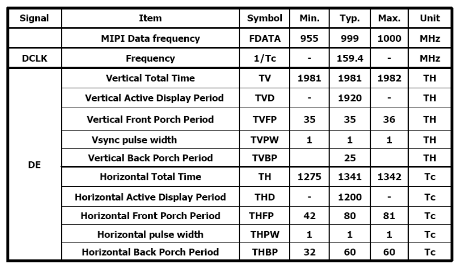
disp_timings0: display-timings {
    native-mode = <&dsi1_timing0>;
    dsi1_timing0: timing0 {
    clock-frequency = <160000000>;
    hactive = <1200>;
    vactive = <1920>;
    hfront-porch = <80>;
    hsync-len = <1>;
    hback-porch = <60>;
    vfront-porch = <35>;
    vsync-len = <1>;
    vback-porch = <25>;
    hsync-active = <0>;
    vsync-active = <0>;
    de-active = <0>;
    pixelclk-active = <1>;
    };
};
Step 3: Open the corresponding DSI node and use the startup logo
//Open the PWM node for backlight
&pwm1_6ch_1 {
    status = "okay";
    pinctrl-names = "active";
    pinctrl-0 = <&pwm1m0_ch1>;
};

&mipidcphy0 {
    status = "okay";
};

&dsi_in_vp1 {
    status = "okay";
};

&vp1 {
    assigned-clocks = <&cru DCLK_VP1_SRC>;
    assigned-clock-parents = <&cru PLL_VPLL>;
}

//Configure DSI to display the startup logo
&route_dsi {
    status = "okay";
};
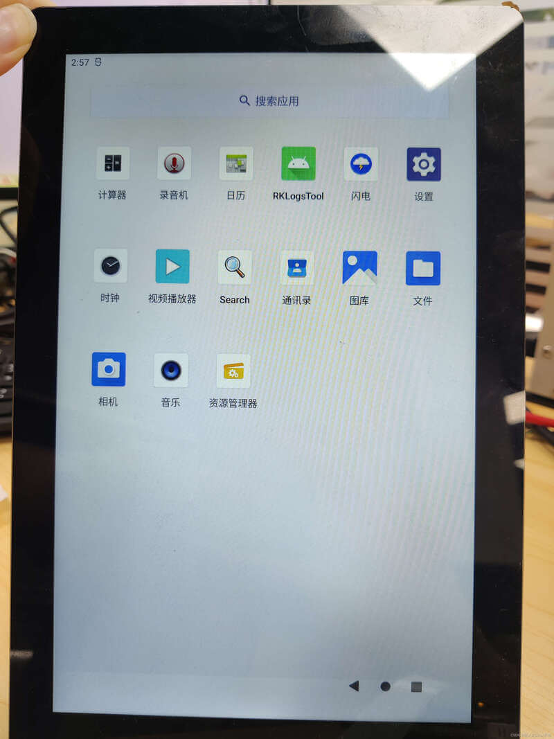
MIPI-DSI Preview
12.4.1.2 Debugging
You can query the status of VOP by using the following command:
cat /sys/kernel/debug/dri/0/summary
The obtained VOP status is shown in the following figure:
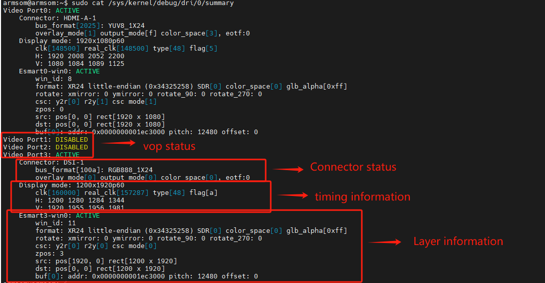 -Video Portx: Table showing the current status of the Video Port
- Connector: The output interface currently connected to the Video Port
- Display mode: Current output timing of Video Port
- Clusterx-winx(Esmartx-winx): Layer Info
12.4.2 DP Screen
The ArmSoM-W3 hardware has a Type-C interface output DP with a resolution of up to 8192x4320@30Hz , The PHY link speed can reach 8.1Gbps/lane.
12.4.2.1 DTS Configuration
The configuration of the DP controller is as follows:
&dp0 {
    status = "okay";
};
&dp0_in_vp2 {
    status = "okay";
};
The PHY configuration is as follows:
&usbdp_phy0 {
&usbdp_phy0 {
    status = "okay";
    orientation-switch;
    svid = <0xff01>;
    sbu1-dc-gpios = <&gpio4 RK_PA6 GPIO_ACTIVE_HIGH>;
    sbu2-dc-gpios = <&gpio4 RK_PA7 GPIO_ACTIVE_HIGH>;

    port {
        #address-cells = <1>;
        #size-cells = <0>;
        usbdp_phy0_orientation_switch: endpoint@0 {
            reg = <0>;
            remote-endpoint = <&usbc0_orien_sw>;
        };

        usbdp_phy0_dp_altmode_mux: endpoint@1 {
            reg = <1>;
            remote-endpoint = <&dp_altmode_mux>;
        };
    };
};
Type-C interface configuration PD chip
The Type-C interface needs to configure the status of lane and HPD through CC detection and PD negotiation of Type-C, so it is also necessary to configure the PD chip (Currently holding PD chips such as fusb302 and husb311):
&i2c4 {
    status = "okay";
    pinctrl-names = "default";
    pinctrl-0 = <&i2c4m1_xfer>;

    usbc0: fusb302@22 {
        compatible = "fcs,fusb302";
        reg = <0x22>;
        interrupt-parent = <&gpio3>;
        interrupts = <RK_PB4 IRQ_TYPE_LEVEL_LOW>;
        int-n-gpios = <&gpio3 RK_PB4 GPIO_ACTIVE_LOW>;
        pinctrl-names = "default";
        pinctrl-0 = <&usbc0_int>;
        //vbus-supply = <&vcc12v_dcin>;
        vbus-supply = <&vbus5v0_typec>;
        status = "okay";

        ports {
            #address-cells = <1>;
            #size-cells = <0>;

            port@0 {
                reg = <0>;
                usbc0_role_sw: endpoint@0 {
                    remote-endpoint = <&dwc3_0_role_switch>;
                };
            };
        };

        usb_con: connector {
            compatible = "usb-c-connector";
            label = "USB-C";
            data-role = "dual";
            power-role = "dual";
            try-power-role = "sink";
            op-sink-microwatt = <1000000>;
            sink-pdos =
                <PDO_FIXED(5000, 3000, PDO_FIXED_USB_COMM)
                 PDO_FIXED(9000, 3000, PDO_FIXED_USB_COMM)
                 PDO_FIXED(12000, 3000, PDO_FIXED_USB_COMM)>;
            source-pdos =
                <PDO_FIXED(5000, 3000, PDO_FIXED_USB_COMM)>;

            altmodes {
                #address-cells = <1>;
                #size-cells = <0>;

                altmode@0 {
                    reg = <0>;
                    svid = <0xff01>;
                    vdo = <0xffffffff>;
                };
            };

            ports {
                #address-cells = <1>;
                #size-cells = <0>;

                port@0 {
                    reg = <0>;
                    usbc0_orien_sw: endpoint {
                        remote-endpoint = <&usbdp_phy0_orientation_switch>;
                    };
                };

                port@1 {
                    reg = <1>;
                    dp_altmode_mux: endpoint {
                        remote-endpoint = <&usbdp_phy0_dp_altmode_mux>;
                    };
                };
            };
        };
    };
};
Configure DP startup logo
&route_dp0 {
    status = "okay";
    connect = <&vp2_out_dp0>;
};
It should be noted that the connect attribute of this configuration allows DP to bind VOP Port2 during the U-Boot phase, so the configuration in dtsi should allow DP to bind VOP Port2:
&dp0_in_vp2 {
    status = "okay";
};
Currently, do not use the DP startup logo with Type-C interface!
12.4.2.2 Debugging
Check the status of the connector: In the/sys/class/drm directory, you can see the various cards registered by the driver, where card0-DP-1 are DP display devices
armsom@armsom :~$  ls /sys/class/drm/
card0  card0-DP-1  card0-HDMI-A-1  card0-Writeback-1  card1  renderD128  renderD129  version
Taking card0-DP-1 as an example, the following content is recorded:
armsom@armsom :~$  ls /sys/class/drm/card0-DP-1/
device  dpms  edid  enabled  modes  power  status  subsystem  uevent
Enable to view the enabled status:
armsom@armsom :~$  cat /sys/class/drm/card0-DP-1/enabled
disabled
Status View Connection Status:
armsom@armsom :~$  cat /sys/class/drm/card0-DP-1/status
disconnected
Mandatory Enable/Disable DP
#Mandatory ban on DP
rk3588_s:/ # echo off > /sys/class/drm/card0-DP-1/status
#Mandatory Enable DP
rk3588_s:/ # echo on > /sys/class/drm/card0-DP-1/status
#Restore hot plug detection
rk3588_s:/ # echo detect > /sys/class/drm/card0-DP-1/status
###12.4.3 HDMI Screen
DTS configuration related to HDMI
- kernel\arch\arm64\boot\dts\rockchip\rk3588-armsom-w3.dts
//Enable HDMI0 function
&hdmi0 {
    status = "okay";
};

//Open hardware phy for HDMI0
&hdptxphy_hdmi0 {
    status = "okay";
};

//Configure HDMI0 to VP0
&hdmi0_in_vp0 {
    status = "okay";
};

//Open HDMI0 audio output
&hdmi0_sound {
    status = "okay";
};

//Configure HDMI0 to display the startup logo
&route_hdmi0 {
    status = "okay";
};

//Open the hdmi1 function
&hdmi1 {
    status = "okay";
};

//Open the hardware phy of hdmi1
&hdptxphy_hdmi1 {
    status = "okay";
};

//Configure HDMI1 to VP1
&hdmi1_in_vp1 {
    status = "okay";
};

//Open HDMI1 audio output
&hdmi1_sound {
    status = "okay";
};

//Configure HDMI1 to display the boot logo on top
&route_hdmi1 {
    status = "okay";
};