Product Introduction: Sige5
Let's get to know Sige5 in 5 minutes.
Overview
ArmSoM-Sige5 adopts the second-generation 8nm high-performance AIOT platform Rockchip RK3576, with a 6 TOPS computing power NPU and support for up to 16GB of large memory. It supports 4K video encoding and decoding, offers rich interfaces including dual gigabit Ethernet ports, WiFi 6 & BT5, and various video outputs. Compatible with multiple operating systems, it is suitable for ARM-based PCs, edge computing devices, personal mobile internet devices, and other digital multimedia applications.
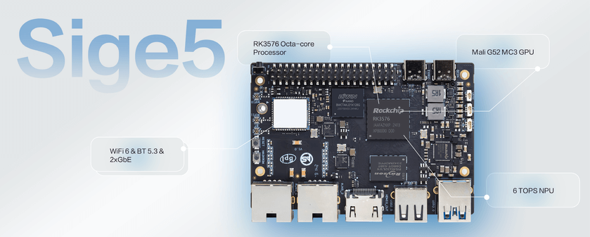
- ArmSoM-Sige5 Single Board Computer;
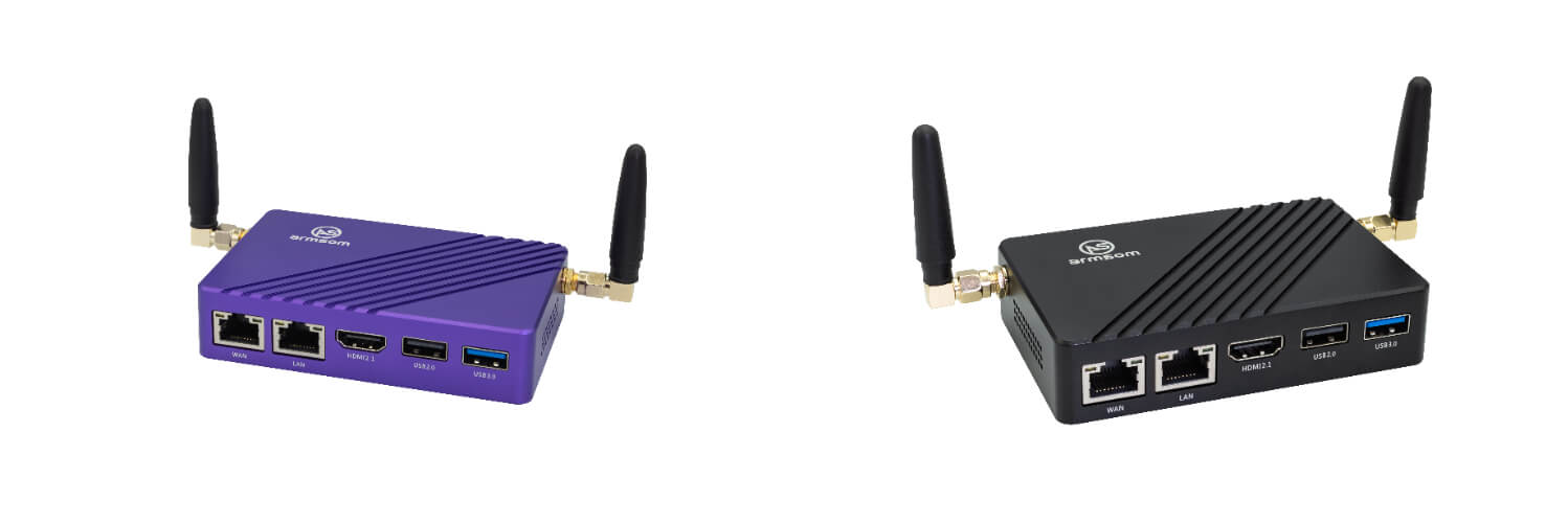
- ArmSoM-CM5 RK3576 CM5 Compute Module, ArmSoM-CM5-IO CM5 companion IO board;
Leveraging a robust ecosystem and a variety of expansion accessories, ArmSoM helps users easily transition from concept to prototype to mass production, making it an ideal creative platform for makers, dreamers, and hobbyists.
Key Parameter
- SoC: Rockchip RK3576
- CPU: Integrated with four Cortex-A72 cores @ 2.2GHz and four Cortex-A53 cores @ 1.8GHz, along with a separate NEON co-processor.
- GPU: ARM Mali G52 MC3 GPU
- NPU: Up to 6 TOPs computing power (INT8), supports INT4/INT8/INT16 mixed operations.
- VPU/Codec:
- Hardware Decoding: Supports H.264, H.265, VP9, AV1, and AVS2 up to 8K@30fps or 4K@120fps, and high-quality JPEG decoding up to 4K@60fps.
- Hardware Encoding: Supports H.264 and H.265,JPEG up to 4K@60fps.
- RAM: 8/16GB 32-bit LPDDR4x, default is 8GB. RK3576 supports a maximum of 16GB.
- Flash: 32/64/128GB eMMC, default is 64GB eMMC.
- WIFI/BT: Onboard IEEE 802.11a/b/g/n/ac/ax WIFI6 and BT5.3 syn43752
- Operating Voltage: Wide input voltage range, from 4.5V to 23V (voltage error ±5%).
- Operating Temperature: 0°C to 80°C
- Operating Systems:
- Official Rockchip Support: Android 14, Debian 12, Buildroot
- Third-party Support: Armbian
- PCB: 8-layer PCB board design
- Weight: 43g
- Dimensions: 92mm × 62mm x 14.6mm
Getting started
Sige User Manual
How to start using your Sige
Hardware
Hardware Interface
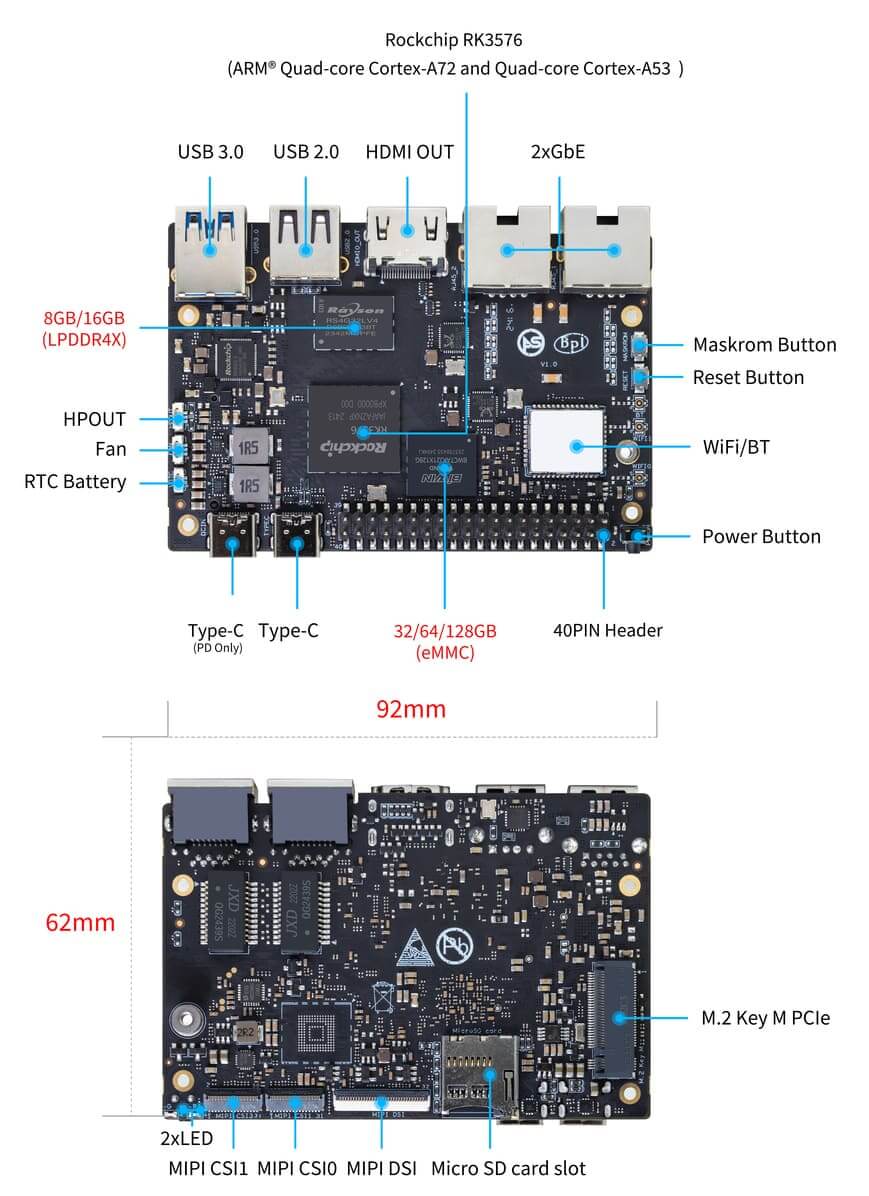
There are two identical Type-C ports on Sige5,but only the Type-C (PD Only) port is for power input.
Hardware Spec
Sige5 Hardware Spec
| Category | Functional Parameters |
|---|---|
| SOC | |
| CPU | |
| GPU | |
| NPU | |
| VPU/Codec | |
| ISP | |
| RAM | |
| Flash | |
| PCIe | |
| Network | |
| Video Output | |
| Video In | |
| Audio | |
| USB Ports | |
| 40-PIN | |
| Other | |
| Power Input | |
| Buttons | |
| OS Support | |
| Dimensions | |
| Operating temperature |
Comparison of Specifications for Sige7/5/3/1
| Sige7 | Sige5 | Sige3 | Sige1 | |
|---|---|---|---|---|
| SoC Process | 8nm | 8nm | 22nm | 28nm |
| CPU | Rockchip RK3588 Cortex-A76 x4 @2.4GHz and Cortex-A55 x4 @1.8GHz | Rockchip RK3576 Cortex-A72 x4 @2.2GHz and Cortex-A53 x4 @1.8GHz | Rockchip RK3568B2 Cortex-A55 x4 @2GHz | Rockchip RK3528 Cortex-A53 x4 @2GHz |
| GPU | ARM Mali-G610 MP4 | ARM Mali G52 MC3 GPU | Arm Mali‑G52‑2EE | ARM Mali-450 GPU |
| NPU | 6TOPS@INT8(3 NPU core) | 6TOPS@INT8(2 NPU core) | 1TOP@INT8 | - |
| RAM | 4GB/8GB/16GB/32GB 64-bit LPDDR4x | 4/8/16GB 32-bit LPDDR4x | 2/4GB 32-bit LPDDR4x | 2/4GB 32-bit LPDDR4x |
| eMMC | 64GB/128GB eMMC | 32/128GB eMMC | 32GB eMMC | 8 eMMC |
| TF Card | Molex Slot, Spec Version 2.x/3.x/4.x(SDSC/SDHC/SDXC) | Yes | Yes | Yes |
| Output | 1x HDMI 2.1, supports 8K@60fps 1x MIPI DSI up to 4K@60fps 1x DP 1.4 up to 8K@30fps | 1x HDMI 2.1, supports 4K@120fps 1x MIPI DSI, up to 2K@60fps 1x DP1.4, up to 4K@120fps | 1x MIPI DSI up to 2K@60fps 1x HDMI OUT2.0, supports 4K@60fps | 1x HDMI OUT2.0b, supports 4K@60fps |
| Decoder | 8K@60fps H.265/VP9/AVS2 8K@30fps H.264 AVC/MVC 4K@60fps AV1 1080P@60fps MPEG-2/-1/VC-1/VP8 | H.264, H.265, VP9, AV1 and AVS2 etc. up to 8K@30fps or4K@120fps | 4KP60 H.265/H.264/VP9 | H.265, H.264, AVS2 4K@60fps |
| Encoder | 8K@30fps H.265 / H.264 | H.264 and H.265 up to 4K@60fps | 1080P60 H.264/H.265 | H.264 and H.265 up to1080@60fps |
| Wi-Fi | AP6275P Wi-Fi 6 Module 802.11a/b/g/n/ac/ax, 2T2R MIMO with RSDB | SYN43752 Wi-Fi 6 Module 802.11a/b/g/n/ac/ax, 2T2R MIMO with RSDB | SYN43752 Wi-Fi 6 Module 802.11a/b/g/n/ac/ax, 2T2R MIMO with RSDBs | SYN43752 Wi-Fi 6 Module 802.11a/b/g/n/ac/ax, 2T2R MIMO with RSDBs |
| PCIE | PCIe 3.0 4-lanes M.2 Key M 2280 NVMe SSD Supported | PCIe 2.1 1-lanes M.2 Key M 2280 NVMe SSD Supported | PCIe 3.0 2-lanes M.2 Key M 2280 NVMe SSD Supported | - |
| Ethernet | 2x 2.5G Ethernet | 2x Gigabit Ethernet | Gigabit Ethernet & 2.5G Ethernet | Gigabit Ethernet & 2.5G Ethernet |
| USB Host | 1x USB 3.0 & 1x USB 2.0 | 1x USB 3.0 & 1x USB 2.0 | 1x USB 3.0 & 1x USB 2.0 | 2x USB 2.0 |
| USB-C | 1x USB-C Power jack & 1x USB Type-C 3.0(DP1.4/OTG) | 1x USB-C Power jack & 1x USB Type-C 3.0(DP1.4/OTG) | 1x USB-C Power jack & 1x USB3.0 OTG | 1x USB-C Power jack & 1x USB2.0 OTG |
| MIPI CSI/DSI | 2x 4-lane MIPI CSI 1x 4-lane MIPI DSI | 2x 4-lane MIPI CSI 1x 4-lane MIPI DSI | 1x 4-lane MIPI CSI 1x 4-lane MIPI DSI | - |
| 40-PIN Header | yes | yes | yes | yes |
| LEDs | 2x LEDs | 2x LEDs | 2x LEDs | 2x LEDs |
| Board Dimensions | 92mm × 62mm x 14.6mm | 92mm × 62mm x 14.6mm | 92mm × 62mm x 14.6mm | 92mm × 62mm x 14.6mm |
RK3576 Block Diagram
RK3576 Block Diagram
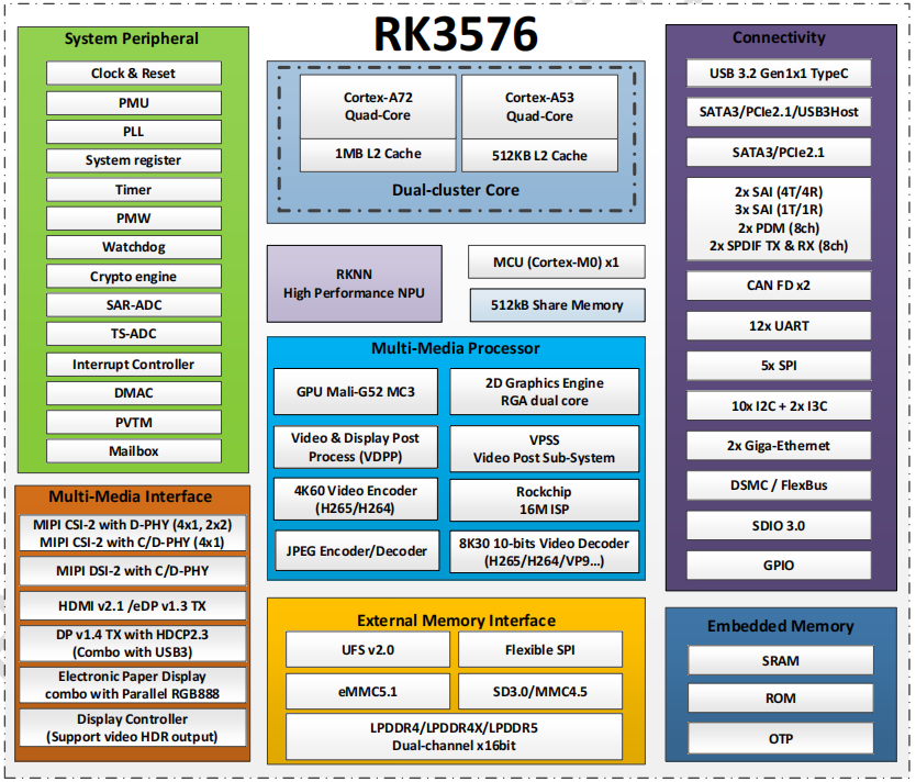
Hardware Pin Definitions
40-PIN header
| GPIO number | Function | Pin | Pin | Function | GPIO number |
|---|---|---|---|---|---|
| +3.3V | 1 | 2 | +5.0V | ||
| 111 | I2C4_SDA_M3 /UART3_CTSN_M1/UART2_RX_M2/GPIO3_B7_d/ | 3 | 4 | +5.0V | |
| 112 | I2C4_SCL_M3/UART3_RTSN_M1 /UART2_TX_M2/GPIO3_C0_d | 5 | 6 | GND | |
| 100 | PWM1_CH0_M3 / SPI2_CLK_M2 / UART1_CTSN_M2 / GPIO3_A4_d | 7 | 8 | GPIO0_D4_u / UART0_TX_M0_PORT / JTAG_TCK_M1 | 28 |
| GND | 9 | 10 | GPIO0_B6/ UART0_RX_M0 /JTAG_TMS_M1 | 14 | |
11 | 12 | SAI0_SCLK_M1 / SPI0_CSN0_M0 / I2C3_SCL_M1 / GPIO0_C6_d | 22 | ||
13 | 14 | GND | |||
15 | 16 | I2C8_SDA_M2 / UART7_RX_M0 / SAI0_LRCK_M0 / GPIO2_B7_d | 79 | ||
| +3.3V | 17 | 18 | I2C8_SCL_M2 / UART7_TX_M0 / GPIO2_B6_d | 78 | |
| 149 | SPI4_MOSI_M0 / PWM2_CH5_M1 /UART6_RX_M3 / I2C3_SDA_M3/GPIO4_C5_d | 19 | 20 | GND | |
| 150 | PWM2_CH2_M1/CAN1_TX_M1 /SPI4_MISO_M0/I2C6_SCL_M3 / GPIO4_C6_d | 21 | 22 | SARADC_VIN4 | |
| 151 | PWM2_CH3_M1/CAN1_RX_M1/SPI4_CLK_M0/I2C6_SDA_M3/ GPIO4_C7_d | 23 | 24 | PWM2_CH6_M1 / UART6_TX_M3 /SPI4_CSN0_M0/ GPIO4_C4_d | 148 |
| GND | 25 | 26 | |||
| 104 | PWM0_CH0_M3 / SPI2_MOSI_M2 / UART10_RX_M0 / GPIO3_B0_d | 27 | 28 | GPIO2_D6_D/PWM2_CH6_M2 / UART9_RTSN_M0 | 94 |
| 119 | GPIO3_C7_D / UART8_RTSN_M0 | 29 | 30 | GND | |
| 128 | GPIO3_D4_D/ I2C3_SCL_M2 / SPI3_CLK_M1 / UART5_RX_M0 | 31 | 32 | ||
| 95 | PWM2_CH7_M2/SPI3_CSN1_M0/UART9_CTSN_M0/SPDIF_TX0_M2/GPIO2_D7_d | 33 | 34 | GND | |
| 20 | PWM0_CH0_M0/UART10_TX_M2/PDM0_CLK0_M0/SAI0_MCLK_M1/GPIO0_C4_d | 35 | 36 | SPI0_CLK_M0/I2C3_SDA_M1/SAI0_LRCK_M1/GPIO0_C7_d | 23 |
| 96 | I2C7_SCL_M1/SPI3_CLK_M0/ UART3_TX_M0/ GPIO3_A0_d D | 37 | 38 | SPI0_MOSI_M0/PDM0_SDI0_M0/SAI0_SDI0_M1/GPIO0_D0_d | 24 |
| GND | 39 | 40 | I3C0_SDA_PU_M0/UART10_RX_M2/ DP_HPDIN_M1/ SAI0_SDO0_M1 / GPIO0_C5_d | 21 |
MIPI CSI0
| Pin | MIPI-CSI | 描述 |
|---|---|---|
| 1,4,7,10,13,16,24,25,26,27,32,33 | GND | Power Ground & Signal Ground |
| 2 | MIPI_DPHY_CSI1_RX_D3N | MIPI RX Lane3 iuput N |
| 3 | MIPI_DPHY_CSI1_RX_D3P | MIPI RX Lane3 iuput P |
| 5 | MIPI_DPHY_CSI1_RX_D2N | MIPI RX Lane2 iuput N |
| 6 | MIPI_DPHY_CSI1_RX_D2P | MIPI RX Lane2 iuput P |
| 8 | MIPI_DPHY_CSI2_RX_CLKN | MIPI RX Clock iuput N |
| 9 | MIPI_DPHY_CSI2_RX_CLKP | MIPI RX Clock iuput P |
| 11 | MIPI_DPHY_CSI1_RX_D1N | MIPI RX Lane1 iuput N |
| 12 | MIPI_DPHY_CSI1_RX_D1P | MIPI RX Lane1 iuput P |
| 14 | MIPI_DPHY_CSI1_RX_D0N | MIPI RX Lane0 iuput N |
| 15 | MIPI_DPHY_CSI1_RX_D0P | MIPI RX Lane0 iuput P |
| 17 | MIPI_DPHY_CSI1_RX_CLKN | MIPI RX Clock iuput N |
| 18 | MIPI_DPHY_CSI1_RX_CLKP | MIPI RX Clock iuput P |
| 19 | MIPI_CSI1_RX_XVS | |
| 20 | MIPI_DPHY_CSI2_CAM_CLKOUT_CON | 1.8V, CLock ouput for Sensor |
| 21 | MIPI_CSI1_RX_XHS | |
| 22 | MIPI_DPHY_CSI1_CAM_CLKOUT | 1.8V, CLock ouput for Sensor |
| 23 | MIPI_DPHY_CSI1_PDN_H(GPIO3_D0) | 1.8V, GPIO |
| 24 | I2C5_SCL_M3_MIPI_CSI1 | 1.8V, I2C Clock, pulled up to 1.8V with 2.2K on sige5 |
| 25 | I2C5_SDA_M3_MIPI_CSI1 | 1.8V, I2C Clock, pulled up to 1.8V with 2.2K on sige5 |
| 26 | MIPI_DPHY_CSI2_PDN_H(GPIO3_C7) | 1.8V, GPIO |
| 27 | MIPI_DPHY_CSI1/2_RST(GPIO3_C6) | 3.3V, GPIO |
| 28,29 | VCC_RX | 3.3V Power ouput |
| 30,31 | VCC_5V0 | 5V Power ouput |
MIPI CSI1
| Pin | MIPI-CSI | Description |
|---|---|---|
| 1,4,7,10,13,16,24,25,26,27,32,33 | GND | Power Ground & Signal Ground |
| 2 | MIPI_DPHY_CSI1_RX_D3N | MIPI RX Lane3 iuput N |
| 3 | MIPI_DPHY_CSI1_RX_D3P | MIPI RX Lane3 iuput P |
| 5 | MIPI_DPHY_CSI1_RX_D2N | MIPI RX Lane2 iuput N |
| 6 | MIPI_DPHY_CSI1_RX_D2P | MIPI RX Lane2 iuput P |
| 8 | MIPI_DPHY_CSI2_RX_CLKN | MIPI RX Clock iuput N |
| 9 | MIPI_DPHY_CSI2_RX_CLKP | MIPI RX Clock iuput P |
| 11 | MIPI_DPHY_CSI1_RX_D1N | MIPI RX Lane1 iuput N |
| 12 | MIPI_DPHY_CSI1_RX_D1P | MIPI RX Lane1 iuput P |
| 14 | MIPI_DPHY_CSI1_RX_D0N | MIPI RX Lane0 iuput N |
| 15 | MIPI_DPHY_CSI1_RX_D0P | MIPI RX Lane0 iuput P |
| 17 | MIPI_DPHY_CSI1_RX_CLKN | MIPI RX Clock iuput N |
| 18 | MIPI_DPHY_CSI1_RX_CLKP | MIPI RX Clock iuput P |
| 19 | MIPI_CSI1_RX_XVS | |
| 20 | MIPI_DPHY_CSI2_CAM_CLKOUT_CON | 1.8V, CLock ouput for Sensor |
| 21 | MIPI_CSI1_RX_XHS | |
| 22 | MIPI_DPHY_CSI1_CAM_CLKOUT | 1.8V, CLock ouput for Sensor |
| 23 | MIPI_DPHY_CSI1_PDN_H(GPIO3_D0) | 1.8V, GPIO |
| 24 | I2C5_SCL_M3_MIPI_CSI1 | 1.8V, I2C Clock, pulled up to 1.8V with 2.2K on sige5 |
| 25 | I2C5_SDA_M3_MIPI_CSI1 | 1.8V, I2C Clock, pulled up to 1.8V with 2.2K on sige5 |
| 26 | MIPI_DPHY_CSI2_PDN_H(GPIO3_C7) | 1.8V, GPIO |
| 27 | MIPI_DPHY_CSI1/2_RST(GPIO3_C6) | 3.3V, GPIO |
| 28,29 | VCC_RX | 3.3V Power ouput |
| 30,31 | VCC_5V0 | 5V Power ouput |
MIPI DSI
| Pin | MIPI-DSI | Description |
|---|---|---|
| 1,4,7,10,13,16,27,33,34 | GND | Power and Signal Ground |
| 2 | MIPI_DPHY_DSI_TX_D0N | MIPI1 TX Lane0 ouput N |
| 3 | MIPI_DPHY_DSI_TX_D0P | MIPI1 TX Lane0 ouput P |
| 5 | MIPI_DPHY_DSI_TX_D1N | MIPI1 TX Lane1 ouput N |
| 6 | MIPI_DPHY_DSI_TX_D1P | MIPI1 TX Lane1 ouput P |
| 8 | MIPI_DPHY_DSI_TX_CLKN | MIPI1 TX Clock ouput N |
| 9 | MIPI_DPHY_DSI_TX_CLKP | MIPI1 TX Clock ouput P |
| 11 | MIPI_DPHY_DSI_TX_D2N | MIPI1 TX Lane2 ouput N |
| 12 | MIPI_DPHY_DSI_TX_D2P | MIPI1 TX Lane2 ouput P |
| 14 | MIPI_DPHY_DSI_TX_D3N | MIPI1 TX Lane3 ouput N |
| 15 | MIPI_DPHY_DSI_TX_D3P | MIPI1 TX Lane3 ouput P |
| 17 | LCD_BL_PWM1_CH1_M0 | 1.8V, GPIO/PWM |
| 18,19 | VCC3V3_LCD | 3.3V Power ouput |
| 20 | LCD_RESET | 1.8V, GPIO |
| 21 | /NC | No Connection |
| 22 | LCD_BL_EN_H | 3.3V, GPIO |
| 23 | I2C0_SCL_M1_TP | 1.8V, I2C Clock, pulled up to 1.8V with 2.2K on sige5 |
| 24 | I2C0_SDA_M1_TP | 1.8V, I2C Data, pulled up to 1.8V with 2.2K on sige5 |
| 25 | TP_INT_L | 1.8V, GPIO |
| 26 | TP_RST_L | 1.8V, GPIO |
| 28,29 | VCC5V0_LCD | 5V Power ouput |
| 31,32 | VCC_1V8 | 1.8V Power ouput |
FAN
| Pin | Assignment | Description |
|---|---|---|
| 1 | VCC_5V0 | 5V Power ouput |
| 2 | GND | GND |
| 3 | PWM | PWM control |
HPOUT
| Pin | Assignment | Description |
|---|---|---|
| 1 | AOR | right channel |
| 2 | AOL | left channel |
| 3 | GND | GND |
VRTC
| Pin | Assignment | Description |
|---|---|---|
| 1 | + | Positive pole |
| 2 | - | Negative pole |
Resourcess
Official Image
ArmSoM team uses Debian bullseye as the official operating system.How to Flash Image📤
Download
The following systems have been tested and verified by ArmSoM official:
Network disk address:
Google Drive link| logo | Description | Download |
|---|---|---|
 | debian12 for Sige5 : Debian 12 brings thousands of new and updated software packages, supports multiple desktop environments, and processor architectures including 32-bit and 64-bit PC, ARM, MIPS, and PowerPC. However, one of the biggest changes is the upgrade of the Linux kernel from version 5.10 to 6.1 LTS. | Google Drive link |
| Android14 for Sige5 : Make your device more personal, protected and accessible with the newest OS upgrade. Improved photo quality, new themes and AI generated wallpapers. Privacy updates for your health, safety and data. And expanded accessibility features. | Google Drive link |
Third Party System
| logo | Description | Download |
|---|---|---|
 | Armbian for Sige5 : Armbian is a computing build framework that allows users to create ready-to-use images with working kernels in variable user space configurations for various single board computers. It provides various pre-build images for some supported boards. These are usually Debian or Ubuntu flavored. | armbian image |
| ubuntu-rockchip for Sige5 : This project aims to provide a default Ubuntu experience for Rockchip RK3588 devices. Get started today with an Ubuntu Server or Desktop image for a familiar environment. | ubuntu-rockchip image | |
| lede | lede for Sige5 : lede is a highly modular and automated embedded Linux system with powerful network components and scalability. | Google Drive link |
Hardware Resources
Product Certificates
Supply Statement
The ArmSoM-Sige5 will be produced at least until July 2034.
Version Change
- Starting from September 25, 2024, orders for ArmSoM-Sige5 will ship with version 1.2, featuring an updated WiFi module (SYN43752 replacing RTL8852BS).
Accessories
The official accessories designed for the ArmSoM-Sige are intended to help you achieve optimal performance from your computer.
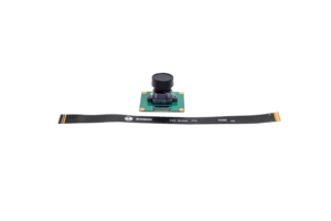
Camera Module 1
The camera module 1, compatible with the OV13850 sensor, is a low-power camera module.

Display-10-HD
A 10.1-inch touchscreen display, ideal for interactive projects like entertainment systems and information dashboards.
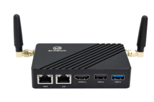
Sige DIY Case 1
Combining high-quality construction with a clean, minimalist design, the metal casing adds a premium touch.
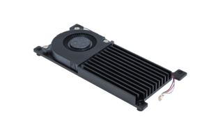
Active Cooling Kit
The active cooling kit ensures Sige runs smoothly even during the most demanding tasks.
Purchase Samples
ArmSoM Official Website: https://www.armsom.org/product-page/sige5
ArmSoM Official AliExpress Store: https://aliexpress.com/item/3256806760032306.html
ArmSoM Official Taobao Store: https://item.taobao.com/item.htm?id=790341533736
For OEM & ODM, please contact: sales@armsom.org
What do others say about the Sige5 ?
- morrolinux: It looks like a Raspberry Pi, but with an NPU for AI.
Notes
- Before handling the device, please ensure you wear an anti-static wrist strap or take electrostatic discharge measures to prevent damage to the development board.
- Assembly should be performed in an electrostatic-safe environment, avoiding operations in dry and low-humidity conditions.
- When not in use, store the device in an anti-static bag and keep it in a suitably temperature-controlled, low-humidity environment to prevent static electricity buildup.
- When handling the device, avoid friction or collisions to prevent the generation of static electricity that could cause damage.
- When holding the device, try to avoid direct contact with the chips on the mainboard to prevent static damage.
- Do not plug or unplug wires or other devices while the device is operating to avoid damage from electrical surges.
- When connecting or disconnecting the GPIO/MIPI expansion interfaces, make sure to turn off the power and disconnect the power cable to prevent damage from electrical current.
Without effective cooling measures, the surface temperature of the main chip may exceed 60 degrees. When handling the device, please avoid direct contact with the SoC and surrounding power inductors to prevent burns. Ensure that the environment is well-ventilated during operation to prevent localized heat buildup, which could lead to overheating. Additionally, do not place the device in direct sunlight. It is recommended to choose between the official cooling fan, heat sink, or third-party cooling kits based on specific usage conditions to ensure optimal cooling performance.