UART Usage
1. UART Introduction
Rockchip UART (Universal Asynchronous Receiver/Transmitter) is based on the 16550A serial port standard, and the complete module supports the following functions:
- Supports 5, 6, 7, 8 data bits.
- Supports 1, 1.5, 2 stop bits.
- Supports odd parity and even parity, but does not support mark parity and space parity.
- Supports receive FIFO and transmit FIFO, generally 32 bytes or 64 bytes.
- Supports up to 4M baud rate, the actual supported baud rate needs to cooperate with the chip clock division strategy.
- Supports interrupt transfer mode and DMA transfer mode.
- Supports hardware automatic flow control, RTS+CTS.
2. Standard UART
- In ArmSoM-Sige7, standard UART is integrated in the 40PIN and can be reused for UART function by users.
- The UARTs that can be reused in the 40PIN are: uart2-m2, uart3-m1, uart4-m2, uart7-m1, uart7-m2, uart8-m0
2.1 How to use the UART in the 40PIN?
Users only need to refer to the overlay setting, and add the UART's overlay file in the overlay properties:
For example:
- Use UART3:
overlays=rk3588-uart3-m1
- Use uart4
overlays=rk3588-uart4-m2
- Use uart7
overlays=rk3588-uart7-m1
- Use uart8
overlays=rk3588-uart8-m0
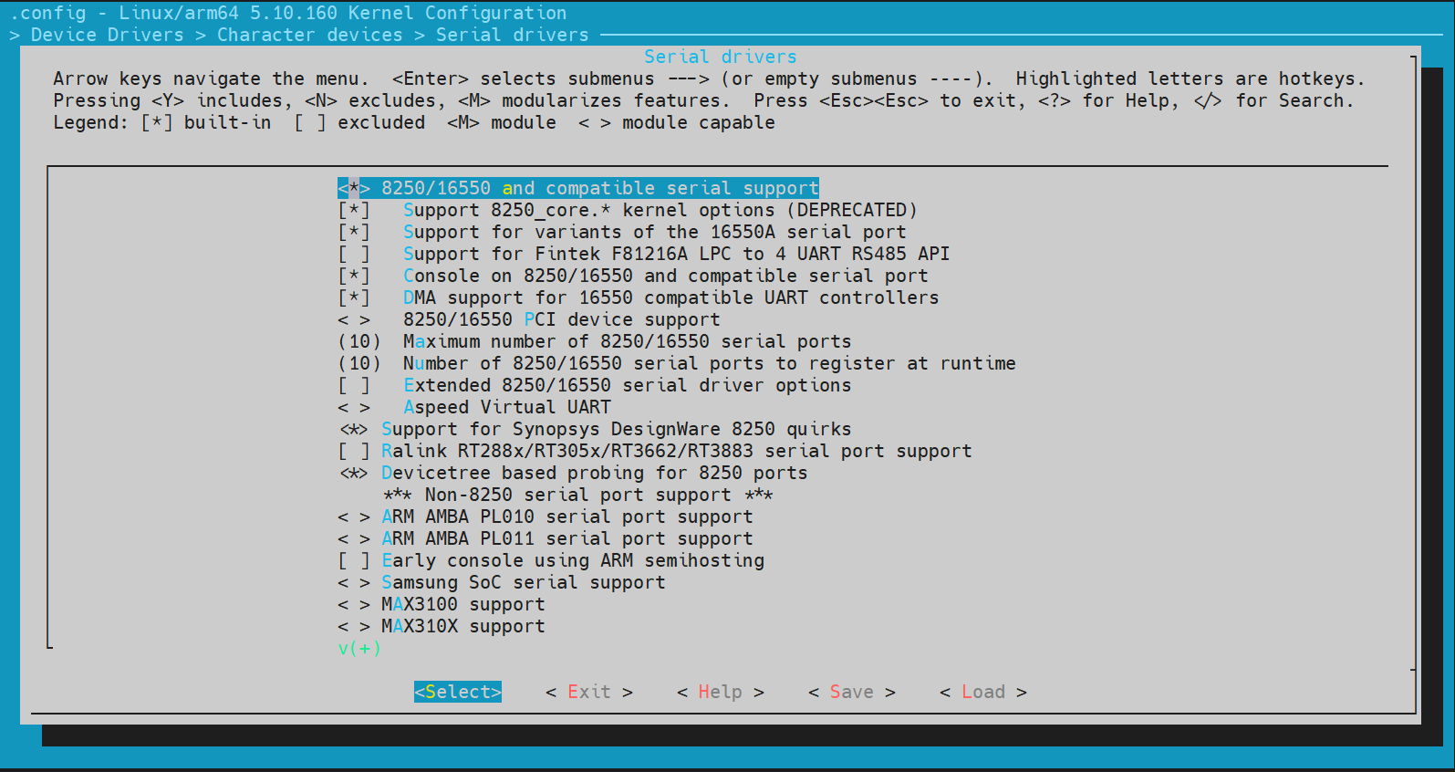
2.2 Kernel menuconfig configuration
Device Drivers() ---> Character devices() ---> Serial drivers
2.3 dts configuration
2.3.1 Chip-level common configuration
kernel/arch/arm64/boot/dts/rockchip/rk3588s.dtsi
uart2: serial@feb50000 {
        compatible = "rockchip,rk3588-uart", "snps,dw-apb-uart";
        reg = <0x0 0xfeb50000 0x0 0x100>;
        interrupts = <GIC_SPI 333 IRQ_TYPE_LEVEL_HIGH>;
        clocks = <&cru SCLK_UART2>, <&cru PCLK_UART2>;
        clock-names = "baudclk", "apb_pclk";
        reg-shift = <2>;
        reg-io-width = <4>;
        dmas = <&dmac0 10>, <&dmac0 11>;
        pinctrl-names = "default";
        pinctrl-0 = <&uart2m1_xfer>;
        status = "disabled";
    };
2.3.2 Board-level configuration
kernel/arch/arm64/boot/dts/rockchip/rk3588-armsom-sige7.dts
The board-level dts configuration for UART allows modifications to the following parameters:
dma-names:
- "tx" enable tx dma
- "rx" enable rx dma
- "!tx" disable tx dma
- "!rx" disable rx dma
pinctrl-0:
- &uart1m0_xfer configure tx and rx pins as iomux group 0
- &uart1m1_xfer configure tx and rx pins as iomux group 1
- &uart1m0_ctsn and &uart1m0_rtsn configure hardware automatic flow control cts and rts pins as iomux group 0
- &uart1m1_ctsn and &uart1m1_rtsn configure hardware automatic flow control cts and rts pins as iomux group 1
status:
- "okay" enable
- "disabled"
For example, to reuse pins 36 and 38 of the 40PIN as uart2:
&uart2 {
    status = "okay";
    pinctrl-names = "default";
    pinctrl-0 = <&uart2m2_xfer>;
}
2.4 UART device node
After configuring the serial port, the hardware interfaces correspond to the following software nodes:
UART3:   /dev/ttyS3
UART4:   /dev/ttyS4
...
2.5 Using serial port to wake up the system
The serial port wake-up system function keeps the serial port open when the system is in sleep mode and sets the serial port interrupt as the wake-up source. To use this function, you need to add the following parameters in the dts:
&uart1 {
    wakeup-source;
};
3. Console UART
- In ArmSoM-Sige7, UART2 is used as the console serial port, which allows users to view boot-up information and perform daily debugging.
3.1 Driver
kernel/drivers/soc/rockchip/fiq_debugger/rk_fiq_debugger.c
3.2 dts configuration
Since fiq_debugger and the standard serial port are mutually exclusive, after enabling the fiq_debugger node, the corresponding standard uart node must be disabled.
fiq_debugger: fiq-debugger {
        compatible = "rockchip,fiq-debugger";
        rockchip,serial-id = <2>;
        rockchip,wake-irq = <0>;
        /* If enable uart uses irq instead of fiq */
        rockchip,irq-mode-enable = <1>;
        rockchip,baudrate = <1500000>;  /* Only 115200 and 1500000 */
        interrupts = <GIC_SPI 423 IRQ_TYPE_LEVEL_LOW>;
        pinctrl-names = "default";
        pinctrl-0 = <&uart2m0_xfer>;
        status = "okay";
    };

&uart2 {
    status = "disabled";
};
The following explains some of the parameters:
- rockchip,serial-id: The UART number used. Changing the serial-id to a different UART will also register the fiq_debugger device as the ttyFIQ0 device.
- rockchip,irq-mode-enable: Configure 1 to use irq interrupt, configure 0 to use fiq interrupt.
- interrupts: Configure the auxiliary interrupt, keep it as default.
4. Testing
UART debugging provides an official test program: ts_uart.uart (stored in the network disk: 1. Development Tools->Test Tools), and two test files send_0x55 and send_00_ff. This program can be obtained by contacting the ArmSoM customer service. Use the adb tool to put the test program on the development board in an executable path, here it is placed in the data path:
adb root
adb remount
adb push ts_uart.uart /data
adb push send_0x55 /data
adb push send_00_ff /data
Modify the test program permissions on the development board:
sudo chmod +x /data/ts_uart.uart
Use the following command to get program help:
console:/ # ./data/ts_uart.uart
Use the following format to run the HS-UART TEST PROGRAM
ts_uart v1.1
For sending data:
./ts_uart <tx_rx(s/r)> <file_name> <baudrate> <flow_control(0/1)> <max_delay(0-
100)> <random_size(0/1)>
tx_rx : send data from file (s) or receive data (r) to put in file
file_name : file name to send data from or place data in
baudrate : baud rate used for TX/RX
flow_control : enables (1) or disables (0) Hardware flow control using RTS/CTS
lines
max_delay : defines delay in seconds between each data burst when sending.
Choose 0 for continuous stream.
random_size : enables (1) or disables (0) random size data bursts when sending.
Choose 0 for max size.
max_delay and random_size are useful for sleep/wakeup over UART testing. ONLY
meaningful when sending data
Examples:
Sending data (no delays)
ts_uart s init.rc 1500000 0 0 0 /dev/ttyS0
loop back mode:
ts_uart m init.rc 1500000 0 0 0 /dev/ttyS0
receive, data must be 0x55
ts_uart r init.rc 1500000 0 0 0 /dev/ttyS0
4.1 Test sending
The command is as follows. send_0x55 and send_00_ff are the files to be sent:
./data/ts_uart.uart s ./data/send_0x55 1500000 0 0 0 /dev/ttyS3
./data/ts_uart.uart s ./data/send_00_ff 1500000 0 0 0 /dev/ttyS3
Successful sending can be verified by connecting a USB-to-UART board to a PC and using a PC serial port debugging tool.
4.2 Test receiving
The command is as follows, and receive_0x55 is the file to receive:
./data/ts_uart.uart r ./data/receive_0x55 1500000 0 0 0 /dev/ttyS1
You can use a PC serial port debugging tool to send data, and the test program will automatically detect it. If U (0x55) is detected, it means the reception is correct; if other characters are detected, it will print the hexadecimal ASCII code value, which can be cross-referenced to check if the reception is correct.
4.3 Test internal self-sending and self-receiving
The command is as follows:
./data/ts_uart.uart m ./data/send_00_ff 1500000 0 0 0 /dev/ttyS3
Press Ctrl+C to stop the test, and you can observe the end log as follows. Compare the sent and received data to see if they are consistent:
Sending data from file to port...
send:1172, receive:1172 total:1172 # Sent and received data are consistent, test passed
send:3441, receive:3537 total:3441 # Sent and received data are inconsistent, test failed
If the test fails, it means that the current serial port has a problem or other programs are also using the same serial port. You can use the following command to see which programs have opened this serial port:
lsof | grep ttyS3