Product Introduction: AIM-IO
AIM-IO is an IO board from the ArmSoM AIM series, with dimensions of 100x80x29 mm, and is also compatible with current Jetson Nano core modules. It is a mini AI computer designed for makers, learners, and developers, capable of quickly implementing AI technology in various smart devices.
Hardware
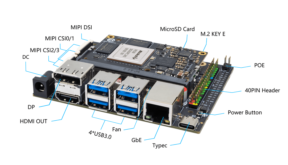
Hardware Interface
The AIM-IO Board is powered by 12V DC.
Hardware Spec
The AIM-IO Board is a companion board for AIM modules designed to assist developers using AIM modules in completing system and embedded board development. Compared to the Jetson Nano Developer Kit (B01), the AIM-IO Board is of the same size but adds 2 MIPI CSI interfaces, 1 M.2 Key-E interface, and 1 MIPI DSI interface.
- 1x DisplayPort
- 1x HDMI-out
- 4x USB 3.0 Type-A
- Gigabit Ethernet
- GPIO: 40-PIN expansion header
- POE: 5 V Power Over Ethernet
- Power Connector: DC Barrel jack for 12V power input
- Expansion: M.2 (E-key, PCIe/USB/SDIO/UART), microSD
- MIPI DSI: 1x 4 lanes MIPI DSI up to 4K@60fps (x4)
- MIPI CSI0/1: 2x 2 lanes MIPI CSI,Maximum 2.5Gbps per lane.
- MIPI CSI2/3: 1x 4 lanes MIPI CSI,Maximum 2.5Gbps per lane.
- Firmware flashing and device mode via USB Type-C
- Dimensions: 100 x 80 x 29 mm (3.94 x 3.15 x 1.14 in)
- Weight: 78.4g
Pin Definition
AIM7 40-PIN Connector
| GPIO Number | Function | Pin | Pin | Function | GPIO Number |
|---|---|---|---|---|---|
| +3.3V | 1 | 2 | +5.0V | ||
| 139 | I2S1_SDO2_M0 / I2C7_SDA_M3 / UART8_CTSN_M0 / PWM15_IR_M1 / CAN1_TX_M1 / GPIO4_B3 | 3 | 4 | +5.0V | |
| 138 | I2S1_SDO1_M0 / I2C7_SCL_M3 / UART8_RTSN_M0 / PWM14_M1 / CAN1_RX_M1 / GPIO4_B2 | 5 | 6 | GND | |
| 115 | SPI1_CS1_M1 / I2C8_SDA_M4 / UART7_CTSN_M1 / PWM15_IR_M0 / GPIO3_C3 | 7 | 8 | GPIO0_B5 / UART2_TX_M0 / I2C1_SCL_M0 / I2S1_MCLK_M1 / JTAG_TCK_M2 | 13 |
| GND | 9 | 10 | GPIO0_B6 / UART2_RX_M0 / I2C1_SDA_M0 / I2S1_SCLK_M1 / JTAG_TMS_M2 | 14 | |
| 113 | SPI1_CLK_M1 / UART7_RX_M1 / GPIO3_C1 | 11 | 12 | GPIO3_B5 / CAN1_RX_M0 / PWM12_M0 / UART3_TX_M1 / I2S2_SCLK_M1 | 109 |
| 111 | SPI1_MOSI_M1 / I2C3_SCL_M1 / GPIO3_B7 | 13 | 14 | GND | |
| 112 | SPI1_MISO_M1 / I2C3_SDA_M1 / UART7_TX_M1 / GPIO3_C0 | 15 | 16 | GPIO3_A4 / SPI4_CS1_M1 / I2S3_SDI / UART8_RTSN_M1 | 100 |
| +3.3V | 17 | 18 | GPIO4_C4 / PWM5_M2 / SPI3_MISO_M0 | 148 | |
| 42 | SPI0_MOSI_M2 / UART4_RX_M2 / GPIO1_B2 | 19 | 20 | GND | |
| 41 | SPI0_MISO_M2 / GPIO1_B1 | 21 | 22 | SARADC_IN4 | |
| 43 | SPI0_CLK_M2 / UART4_TX_M2 / GPIO1_B3 | 23 | 24 | GPIO1_B4 / UART7_RX_M2 / SPI0_CS0_M2 | 44 |
| GND | 25 | 26 | GPIO1_B5 / UART7_TX_M2 / SPI0_CS1_M2 | 45 | |
| 150 | SPI3_CLK_M0 / I2C0_SDA_M1 / PWM7_IR_M3 / GPIO4_C6 | 27 | 28 | GPIO4_C5 / PWM6_M2 / I2C0_SCL_M1 | |
| 63 | UART1_CTSN_M1 / PWM15_IR_M3 / GPIO1_D7 | 29 | 30 | GND | |
| 47 | SPDIF_TX_M0 / UART1_RX_M1 / PWM13_M2 / GPIO1_B7 | 31 | 32 | GPIO3_C2 / PWM14_M0 / UART7_RTSN_M1 / I2C8_SCL_M4 / SPI1_CS0_M1 | 114 |
| 103 | PWM8_M0 / GPIO3_A7 | 33 | 34 | GND | |
| 110 | I2S2_LRCK_M1 / UART3_RX_M1 / PWM13_M0 / CAN1_TX_M0 / GPIO3_B6 | 35 | 36 | GPIO3_B1 / PWM2_M1 / UART2_TX_M2 | 105 |
| 0 | REFCLK_OUT / GPIO0_A0 | 37 | 38 | GPIO3_B2 / PWM3_IR_M1 / UART2_RX_M2 / I2S2_SDI_M1 | 106 |
| GND | 39 | 40 | GPIO3_B3 / UART2_RTSN / I2S2_SDO_M1 | 107 |
User Manual
The AIM-IO User Manual helps users understand the basic usage of AIM products and the preparations needed to get started with your ArmSoM-AIM 🚀.
Getting Started
Before using the ArmSoM-AIM product, please prepare the following items.
Tools Preparation
- Power Supply
- System Installation (Choose one)
- Onboard eMMC Boot
- USB Type-C data cable to write the image from the Type-C port on the ArmSoM-AIM series. You need to connect the ArmSoM-AIM to your PC using a Type-C data cable.
- MicroSD/TF Card Boot
- MicroSD/TF card, Class 10 or above, at least 8GB SDHC, and a card reader.
- The following high-speed TF cards have been tested and validated by the ArmSoM team:
- SanDisk 32GB TF (MicroSD) (Developer Recommended)
- SanDisk 32GB TF (MicroSD) for Dash Cam & Security Monitoring (Recommended for Long-Term Use)
- SanDisk TF 8GB Class 10 microSD
- SanDisk TF 128GB Class 10 microSD XC 48MB/S
- Onboard eMMC Boot
You can set up the ArmSoM-AIM as an interactive computer with a desktop interface or configure it as a headless computer accessible only via the network. To set up the ArmSoM-AIM as a headless computer, configure the hostname, user account, network connection, and SSH during the initial OS installation. If you want to use the ArmSoM-AIM directly, you will need the following additional accessories:
Optional Items
- Keyboard & Mouse
- HDMI Monitor and HDMI Cable
- Ethernet Cable
- Camera Module
- Recommended: camera-module1.
- LCD Display
- Recommended: Display 10 HD.
Power Supply
The ArmSoM-AIM series requires a power supply specification of 12V/2-3A. You can use any high-quality power supply that provides the correct power mode.
Plug the power supply into the DC barrel jack, ensuring you use the correct port!
Image Burning Options
The system images for the ArmSoM series include various root file systems, and you can choose the appropriate image for your needs.
The system image includes the Linux kernel, basic programs, etc., which are essential for running ArmSoM series products. Therefore, we need to install the image before operating the product.
Obtaining the System Image
Visit the Baidu Cloud resource introduction page to obtain the system image: Baidu Cloud Link
- The default username/password for the official images is armsom/armsom or root/root.
- Ubuntu, Armbian, and OpenWrt offer more choices for open-source enthusiasts provided by ArmSoM.
Burning Ubuntu, Armbian, or OpenWrt Systems
Using a Card Reader to Burn to MicroSD
Using Etcher to Write the Operating System Image to MicroSD
This method is suitable for writing the system to an SD card and is available on Windows, macOS, and Linux x64 operating systems.
- A microSD card
- An SD card reader
- Download the corresponding Ubuntu / Armbian / OpenWrt system image
- Insert the SD card into the SD reader and connect it to your computer’s USB port
Using Etcher to Write the Operating System Image to MicroSD
- Download balenaEtcher from the balena website, selecting the version for your host operating system. The Linux version is in AppImage format.
- Insert the MicroSD card into the MicroSD reader.
- Open the Etcher window, select "Flash from file," and locate your downloaded image. Double-click to select it.

- Click "Select target" to choose the MicroSD card you want to burn to.
- Click "Flash" and wait for the process to complete; this may take some time.
- Upon successful burning, you will see a confirmation message.

- On Windows, the image burning process needs to be "Run as Administrator." Some Linux users may need to use the
chmodcommand to make it executable. - If the image writing fails, please try again.
Using Win32DiskImager to Write the Operating System Image to MicroSD
- Download the Win32DiskImager tool.
- Open Win32DiskImager.
- Click the folder icon and select the image you want to write.
- After completing the previous steps, click the "Write" button to start writing the image and wait for the process to finish.
Using USB Cable to Burn to eMMC
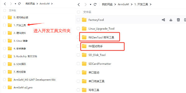
Tool Acquisition and Installation
Burning the image to eMMC requires the RKDevTool burning tool and the RK Driver Assistant (Driver Assistant).
Click the link: Baidu Cloud Link
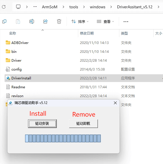
Installing Driver Assistant
Unzip the Driver Assistant software package and double-click DriverInstall.exe to enter the driver installation interface.
Click "Driver Install" to start the installation. If you're unsure whether an old version of the driver is already installed, first click "Driver Uninstall" to remove it, then click "Driver Install."
Installing RKDevTool
RKDevTool is a dedicated USB burning tool for Rockchip products on the Windows platform, allowing you to download the system image to the product via USB.
After unzipping the package, it can be used without installation; double-click RKDevTool.exe to access the software interface.
The software has three main sections: download the image (to burn the image according to the address), upgrade the firmware, and advanced functions.
MASKROM/Loader Mode for Image Burning
This mode is suitable for products that have not had a system burned or where the burned system is corrupted and cannot run (Applicable to all situations).
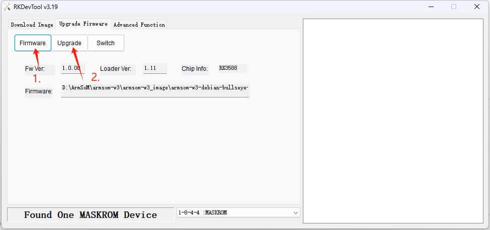
We open the RKDevTool burning tool and set the product to enter burning mode.
Please refer to the product-related instructions for operations; the methods to enter Maskrom mode are generally similar across different products.
1. Prepare a Type-C cable for image burning.
2. Disconnect all possible power connections to the product, such as power cables, USB cables, etc.
3. Connect one end of the Type-C cable to the product's OTG interface and the other end to your computer's USB port, then open the RKDevTool software.
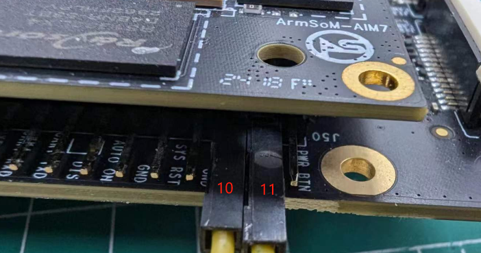
4. Short the 10 and 11 pins on the 12-pin interface (as shown) to enter loader mode, then power the product using DC.
5. Wait for the software to prompt that a MASKROM/LOADER device has been found (as shown below), then you can release the button.
6. If it does not succeed, repeat steps 2-5.
Shorting pins 10 and 11 to enter loader mode.
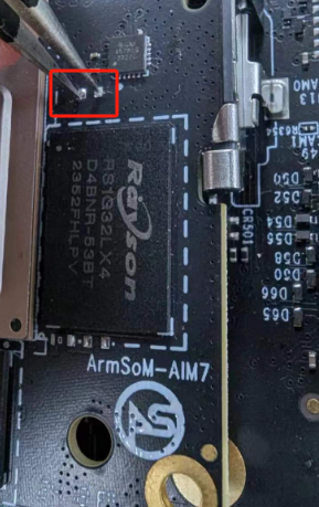
Shorting maskrom test points to enter maskrom mode.
Start burning the system.
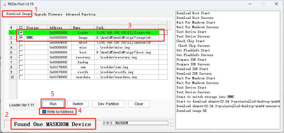
- Select the "Download Image" option.
- Confirm that the board has entered Maskrom mode.
- Click the blank cell to select the MiniLoaderAll and Image files to use; the corresponding MiniLoaderAll and Image are stored on Baidu Cloud.
- In the "Storage" option, select the target medium EMMC, and select "Force Write by Address," then click "Execute."
- Wait for the writing to complete, after which the device will automatically reboot, as shown in the right side of the image with "Download image OK."
Burning Debian System
Using a Card Reader to Burn to MicroSD
Installing SDDiskTool
Burning the image to eMMC requires using the burning tool SDDiskTool_version.exe.
Click the link: Baidu Cloud Link
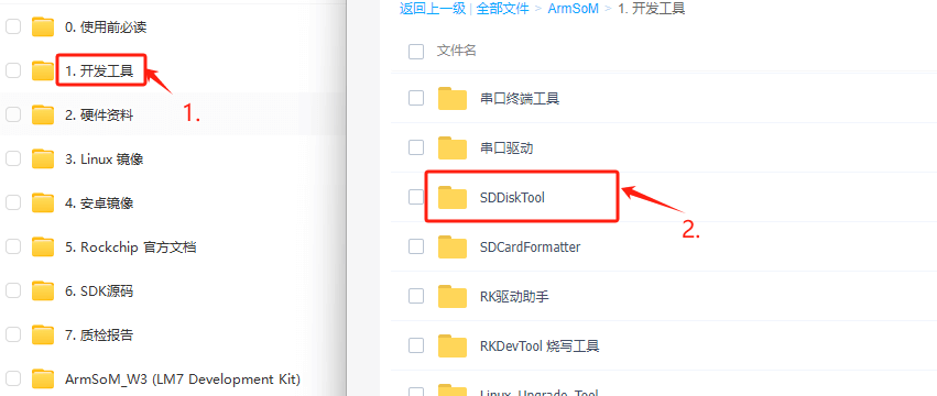
After unzipping the package, you can use it without installation; double-click SD_Firmware_Tool.exe to access the software interface.
Burning the Image
Open the executable file SDDiskTool (SD_Firmware_Tool.exe) and insert the SD card.
First, select the correct SD card to burn, then set the function mode to "SD Boot," select the image to burn, and finally click "Start" to create the burning image on the SD card.

Be patient while the SD card is being burned. If the image is large, the burning time will increase accordingly.
- Clicking "Create" may occasionally result in an error stating that it cannot burn; you can close the error window and try to start creating again. If it still doesn’t work, try formatting the SD card.
- The firmware downloaded from Baidu Cloud needs to be extracted before loading. On Windows PCs, the tool must be run with administrator privileges to execute.
Using USB Cable to Burn to eMMC
We open the RKDevTool burning tool and set the product to enter burning mode.
1. Prepare a Type-C cable for image burning.
2. Disconnect all possible power connections to the product, such as power cables, USB cables, etc.
3. Connect one end of the Type-C cable to the product's OTG interface and the other end to your computer's USB port, then open the RKDevTool software.
4. Press and hold the Recovery button, then power the product using DC.
5. Wait for the software to prompt that a LOADER device has been found (as shown below), then you can release the button.
6. If it does not succeed, repeat steps 2-5.

The flashing progress will be displayed on the right, and upon completion, it will prompt you:
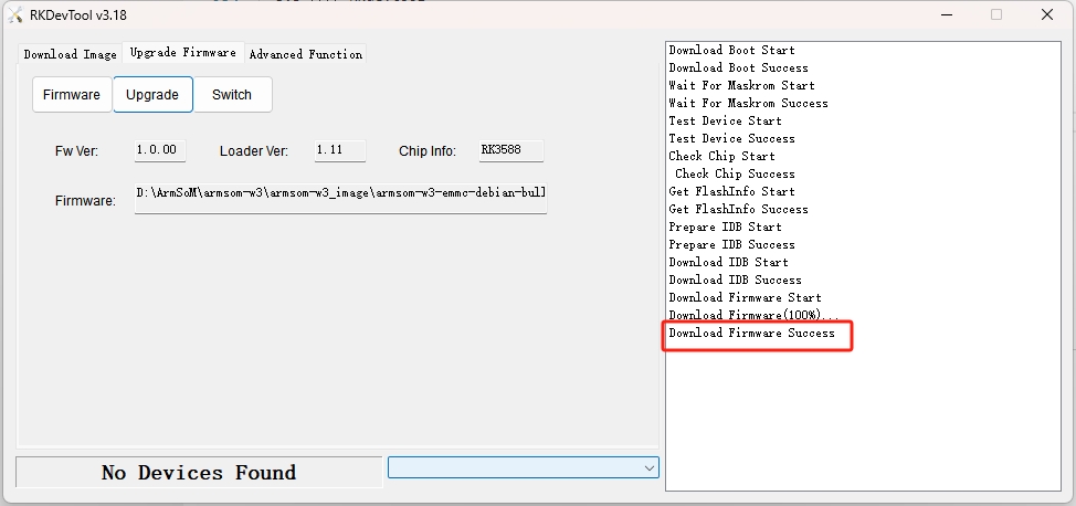
If a "Download Boot Fail" error occurs during the flashing process, or if there are errors during the process, as shown in the image, it is usually due to poor connection with the USB cable, low-quality cables, or insufficient power from the computer's USB port. Please change the USB cable or USB port on the computer to troubleshoot.
Sure! Here’s the translation:
Interface Usage
Debug Serial Port
Connect the USB to TTL serial cable as shown below:
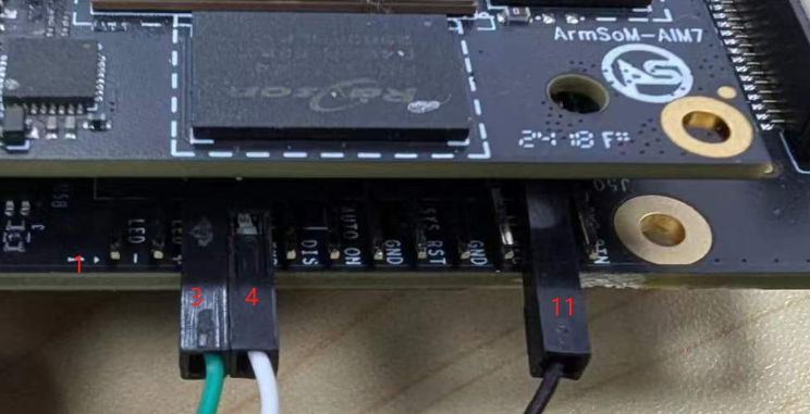
| AIM-IO | Connection | Serial Module |
|---|---|---|
| GND (pin 11) | ---> | GND |
| RX (pin 3) | ---> | TX |
| TX (pin 4) | ---> | RX |
Ethernet Port
- First, plug one end of the Ethernet cable into the ArmSoM-AIM’s Ethernet port and connect the other end to a router, ensuring the network is functional.
- After booting, the system will automatically assign an IP address to the Ethernet card via DHCP without any additional configuration.
- To check the IP address in the ArmSoM-AIM Linux system, use the following command:
root@armsom-aim7:/# ip a
1: lo: <LOOPBACK,UP,LOWER_UP> mtu 65536 qdisc noqueue state UNKNOWN group default qlen 1000
    link/loopback 00:00:00:00:00:00 brd 00:00:00:00:00:00
    inet 127.0.0.1/8 scope host lo
       valid_lft forever preferred_lft forever
    inet6 ::1/128 scope host
       valid_lft forever preferred_lft forever
2: eth0: <BROADCAST,MULTICAST,UP,LOWER_UP> mtu 1500 qdisc mq state UP group default qlen 1000
    link/ether c2:ed:bc:48:3b:7a brd ff:ff:ff:ff:ff:ff
    inet 192.168.10.106/24 brd 192.168.10.255 scope global dynamic noprefixroute eth0
       valid_lft 86396sec preferred_lft 86396sec
    inet6 fe80::7351:88a9:9b4c:11be/64 scope link noprefixroute
       valid_lft forever preferred_lft forever
After the ArmSoM-AIM boots, there are three ways to check the IP address:
- Connect to an HDMI display, log into the system, and use the terminal to enter the
ip acommand. - Use the debug serial port terminal to enter the
ip acommand to check the IP address. - If there is no debug serial port or HDMI display, you can check the ArmSoM-AIM’s IP address through the router’s management interface. However, this method often fails to display the ArmSoM-AIM’s IP address. If not visible, follow these troubleshooting steps:
- First, check whether the Linux system has booted properly. If the ArmSoM-AIM's green LED is solid, it generally indicates a normal boot. If only the red LED is on, the system hasn't booted correctly.
- Ensure the Ethernet cable is securely connected, or try a different cable.
- Test with another router, as many issues arise from routers not assigning IP addresses correctly or assigning them but not displaying them in the management interface.
- If no alternative router is available, connect an HDMI display or use the debug serial port to check the IP address.
It is important to note that the ArmSoM-AIM automatically assigns an IP address via DHCP without any settings required.
- Use the
pingcommand to check network connectivity.
The command to test network connectivity is as follows. You can interrupt the ping command by using the Ctrl+C shortcut:
armsom@armsom-aim7:~$ ping www.baidu.com
PING www.a.shifen.com (183.2.172.185): 56 data bytes
64 bytes from 183.2.172.185: icmp_seq=0 ttl=53 time=8.370 ms
64 bytes from 183.2.172.185: icmp_seq=1 ttl=53 time=8.917 ms
64 bytes from 183.2.172.185: icmp_seq=2 ttl=53 time=8.511 ms
64 bytes from 183.2.172.185: icmp_seq=3 ttl=53 time=8.673 ms
^C
--- www.a.shifen.com ping statistics ---
4 packets transmitted, 4 packets received, 0% packet loss
round-trip min/avg/max/stddev = 8.370/8.618/8.917/0.203 ms
HDMI
| Model | AIM7 | AIM5 |
|---|---|---|
| Resolution | 8Kp60 | 4Kp120 |
- Use an HDMI cable to connect the ArmSoM-AIM to an HDMI display.
- If the HDMI display outputs an image after the Linux system boots, the HDMI interface is functioning properly.
Note that many laptops have HDMI ports that only support output functionality. This means they cannot display HDMI output from other devices on their screens. When attempting to connect the development board's HDMI to a laptop HDMI port, please confirm whether your laptop supports HDMI input functionality. If no display is shown, first check whether the system version includes a desktop environment, as server versions only show the terminal.
DP (DisplayPort)
| Model | AIM7 | AIM5 |
|---|---|---|
| Resolution | 4Kp60 | 4Kp60 |
- Use a DP cable to connect the ArmSoM-AIM to a DP display.
- If the DP display outputs an image after the Linux system boots, the DP interface is functioning properly.
USB
| Model | AIM7 |
|---|---|
| USB | 1* Type-C 2.0, 4x USB3.0 |
The USB interface can be connected to a USB hub to expand the number of USB ports.
Connecting USB Mouse or Keyboard Test
- Plug a USB keyboard into the ArmSoM-AIM's USB port.
- Connect the ArmSoM-AIM to an HDMI display.
- If the mouse or keyboard operates normally within the system, the USB interface is functioning properly (note: the mouse works only in desktop versions).
Connecting USB Storage Device Test
- First, insert a USB flash drive or external USB hard drive into the ArmSoM-AIM's USB port.
- Execute the following command; if you see output for
sdX, it indicates the USB drive is recognized:
armsom@armsom-aim7:/# cat /proc/partitions | grep "sd*"
major minor  #blocks  name
   8        0  122880000 sda
- Use the
mountcommand to mount the USB drive to/mnt, allowing you to view files on the drive:
armsom@armsom-aim7:/# sudo mount /dev/sda1 /test/
- After mounting, you can check the USB drive’s capacity usage and mount point with the
df -hcommand:
armsom@armsom-aim7:/test# df -h | grep "sd"
/dev/sda        4.7G  4.7G     0  100% /test
USB Camera
Prepare a USB camera that supports UVC protocol and plug it into the ArmSoM-AIM's USB port.
Use the
v4l2-ctlcommand to find the device node information for the USB camera, which will be/dev/video0:
armsom@armsom-aim7:/# v4l2-ctl --list-devices
Logitech HD Webcam C930e (usb-xhci-hcd.5.auto-1):
        /dev/video40
        /dev/video41
        /dev/media4
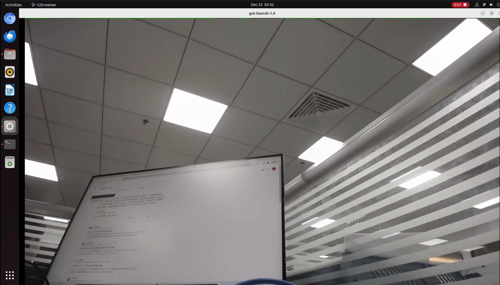
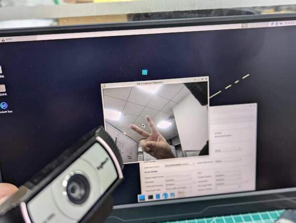
- On the desktop system, you can directly open the USB camera using Cheese/V4L2 test bench:
You can also open the camera preview via terminal command:
armsom@armsom-aim7:/# gst-launch-1.0 v4l2src device=/dev/video0 io-mode=4 ! videoconvert ! video/x-raw,format=NV12,width=1920,height=1080 ! xvimagesink;
To take a photo, use the following command:
armsom@armsom-aim7:/# gst-launch-1.0 v4l2src device=/dev/video0 io-mode=4 ! videoconvert ! video/x-raw,format=NV12,width=1920,height=1080 ! jpegenc ! multifilesink location=/home/armsom/test.jpg;
To record a video, use this command:
gst-launch-1.0 v4l2src num-buffers=512 device=/dev/video0 io-mode=4 ! videoconvert ! video/x-raw, format=NV12, width=1920, height=1080, framerate=30/1 ! tee name=t ! queue ! mpph264enc ! queue ! h264parse ! mpegtsmux ! filesink location=/home/armsom/test.mp4