CM5-IO Product Introduction
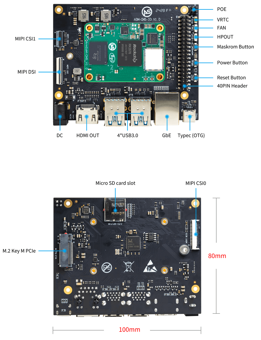
The CM5-IO is the IO board for the ArmSoM CM5, with dimensions of 100x80x29 mm. It is a miniature AI computer designed specifically for makers, learners, and developers, enabling the rapid application of AI technology to various smart devices.
Hardware Information
Hardware Specifications
The CM5-IO board is an expansion board specifically designed for the CM5 computing module, aimed at assisting in system and embedded board development.
- 1x HDMI output, 1x Typec(DP) output
- 4x USB 3.0 Type-A
- Gigabit Ethernet RJ45 with PoE support
- Firmware flashing and device mode via USB Type-C
- GPIO: 40-PIN header
- Power connector: DC Barrel jack for 12V power input
- Expansion: M.2 (M-key, supports PCIe), microSD
- MIPI DSI: 1x 4-lane MIPI DSI, supports up to 4K@60fps (x4)
- MIPI CSI0: 1x 4-lane MIPI CSI, each lane up to 2.5Gbps
- MIPI CSI1: 1x 2-lane MIPI CSI, each lane up to 2.5Gbps
- Others: HPOUT, FAN, VRTC
- Dimensions: 100 x 80 x 29 mm (3.94 x 3.15 x 1.14 inches)
- Weight: 65.2g
Hardware Interfaces
The cm5-io board uses a 12V DC power supply.
Pin Definition
40-PIN header
| GPIO number | Function | Pin | Pin | Function | GPIO number |
|---|---|---|---|---|---|
| +3.3V | 1 | 2 | +5.0V | ||
| 140 | CAN1_RX_M2 / I2C3_SDA_M0 / UART2_RX_M1 / GPIO4_B4_d | 3 | 4 | +5.0V | |
| 141 | CAN1_TX_M2 / I2C3_SCL_M0 / UART2_TX_M1 / GPIO4_B5_d | 5 | 6 | GND | - |
| 20 | PWM0_CH0_M0 / GPIO0_C4_d | 7 | 8 | UART0_TX_M0 / GPIO0_D4_u | 28 |
| - | GND | 9 | 10 | UART0_RX_M0 / GPIO0_D5_u | 29 |
| - | - | 11 | 12 | - | - |
| - | - | 13 | 14 | GND | |
| - | - | 15 | 16 | GPIO2_D1_d / UART4_RX_M0 / I2C6_SDA_M2 / PWM2_CH1_M2 | 89 |
| +3.3V | 17 | 18 | GPIO2_D0_d / UART4_TX_M0 / I2C6_SCL_M2 / PWM2_CH0_M2 | 88 | |
| 97 | I2C7_SDA_M1 / SPI3_MOSI_M0 / UART3_RX_M0 / GPIO3_A1_d | 19 | 20 | GND | - |
| 98 | CAN1_TX_M3 / SPI3_MISO_M0 / SPDIF_RX1_M1 / UART3_CTSN_M0 / GPIO3_A2_d | 21 | 22 | SARADC_VIN4 | - |
| 96 | I2C7_SCL_M1 / SPI3_CLK_M0 / UART3_TX_M0 / GPIO3_A0_d | 23 | 24 | GPIO3_A3_d / CAN1_RX_M3 / SPI3_CSN0_M0 / UART3_RTSN_M0 / SPDIF_TX1_M1 | 99 |
| - | GND | 25 | 26 | - | - |
| 111 | I2C4_SDA_M3 / UART2_RX_M2 / GPIO3_B7_d | 27 | 28 | GPIO2_D6_d / PWM2_CH6_M2 / SAI3_MCLK_M2 | 94 |
| 112 | I2C4_SCL_M3 / UART2_TX_M2 / GPIO3_C0_d | 29 | 30 | GND | - |
| 126 | SPI3_MOSI_M1 / PWM2_CH6_M3 / GPIO3_D6_d | 31 | 32 | - | - |
| - | - | 33 | 34 | GND | - |
| - | - | 35 | 36 | - | - |
| - | - | 37 | 38 | - | - |
| - | GND | 39 | 40 | - | - |
FAN
| Pin | Assignment | Description |
|---|---|---|
| 1 | VCC_5V0 | 5V Power ouput |
| 2 | GND | GND |
| 3 | PWM | PWM control |
HPOUT
| Pin | Assignment | Description |
|---|---|---|
| 1 | AOR | right channel |
| 2 | AOL | left channel |
| 3 | GND | GND |
VRTC
0.8mm connector(J27)
| Pin | Assignment | Description |
|---|---|---|
| 1 | + | Positive pole |
| 2 | - | Negative pole |
PoE In(J5)
| Pin | Assignment | Description |
|---|---|---|
| 1 | VC1 | TX1 |
| 2 | VC2 | RX1 |
| 3 | VC3 | TX2 |
| 4 | VC4 | RX2 |
Resources
ArmSom-bsp
Building a Linux System
Armbian
Armbian Linux build framework
Android14 SDK
Improved Rockchip Android
CM5 kernel
Improved Rockchip Linux
CM5 uboot
ArmSoM/u-boot
RKNN-LLM
AI models to Rockchip chips
Official Images
ArmSoM team uses Debian bullseye as the official operating system.How to Flash Image📤
Download
The following systems have been tested and verified by ArmSoM official:
Network disk address:
Google Drive link| Logo | Description | Download |
|---|---|---|
 | Debian 12 for CM5: Debian 12 introduces thousands of new and updated packages, supporting various desktop environments and processor architectures (including 32-bit and 64-bit PCs, ARM, MIPS, and PowerPC). One of the biggest changes is the upgrade of the Linux kernel from version 5.10 to 6.1 LTS. | Google Drive link |
 | Android 14 for CM5: The latest OS upgrade makes your device more personalized, secure, and accessible. It offers improved photo quality, new themes, and AI-generated wallpapers. Privacy updates protect your health, safety, and data while expanding accessibility features. | Google Drive link |
Third-Party Images
| Logo | Description | Download |
|---|---|---|
| Armbian for CM5: Armbian is a build framework that allows users to create ready-to-use images with a working kernel based on various user-space configurations for single-board computers. It provides a variety of pre-built images for some supported SBCs, typically based on Debian or Ubuntu. | Armbian Image | |
 | Ubuntu-Rockchip for CM5: This project aims to provide the default Ubuntu experience for Rockchip RK3588 devices. Get started right away by choosing the appropriate Ubuntu server or desktop image, and enjoy a familiar environment. | Ubuntu-Rockchip Image |
Hardware Resources
Get schematics, PCB, DXF, and other hardware documentation for the cm5-io development kit to quickly start your development.
CM5 Hardware ResourcesArmSoM-CM5 pin table - pin table
Getting Started
Preparing for CM5-IO Usage
In the following text, "CM5 Kit" refers to CM5 + CM5-IO.
Tools Preparation
- Power supply
- System Installation (Choose one)
- eMMC Boot
- USB Type-C cable: Use a Type-C cable to write the image to the CM5 Kit through the Type-C port. You will need a Type-C cable to connect the CM5 Kit to your PC.
- MicroSD/TF Card Boot
- MicroSD/TF card: Class 10 or above, at least 8GB SDHC, and a card reader.
- Below are high-speed TF cards tested and verified by the ArmSoM team:
- SanDisk 32GB TF (MicroSD) (Recommended for developers)
- SanDisk 32GB TF (MicroSD) Dashcam & Surveillance-specific storage card (Recommended for long-term operation)
- SanDisk TF 8G Class10 microSD
- SanDisk TF 128G Class10 microSD XC TF 128G 48MB/S
- eMMC Boot
You can set up the CM5 Kit as an interactive desktop computer or as a headless computer that can only be accessed over the network. To set up the CM5 Kit as a headless computer, configure the hostname, user account, network connection, and SSH during the initial OS installation. If you plan to use the CM5 Kit directly, you will need the following additional accessories:
Optional Accessories
- Keyboard & Mouse
- HDMI monitor and HDMI cable
- Ethernet cable
- Camera module
- For a 4-lane camera, it's recommended to use the camera-module1.
- For a 2-lane camera, use the Raspberry Pi camera-module-v2.
- LCD display
- It's recommended to use the Display 10 HD.
- Audio cable, 0.8mm vertical socket.
- RTC battery, 0.8mm vertical socket.
- Fan, 0.8mm vertical socket.
Power Supply
- Supports DC 12V adapter, 2.5mm
Choosing a Flashing Method
Interface Usage
If you are using the CM5 Kit for the first time, please familiarize yourself with the hardware interfaces of each product, which will help you better understand the following content.
Debugging Serial Port
Connect the USB to TTL serial cable as shown below:
| CM5-IO | Connect | Serial Module |
|---|---|---|
| GND (pin 6) | ---> | GND |
| TX (pin 8) | ---> | RX |
| RX (pin 10) | ---> | TX |
Ethernet Port
- First, insert one end of the Ethernet cable into the CM5 Kit's Ethernet port, and connect the other end to the router, ensuring that the network is functioning properly.
- After the system starts, an IP address will be automatically assigned to the Ethernet card via DHCP, with no additional configuration needed.
- To view the IP address in the Linux system on the CM5 Kit, use the following command:
root@armsom-cm5:/# ip a
1: lo: <LOOPBACK,UP,LOWER_UP> mtu 65536 qdisc noqueue state UNKNOWN group default qlen 1000
    link/loopback 00:00:00:00:00:00 brd 00:00:00:00:00:00
    inet 127.0.0.1/8 scope host lo
       valid_lft forever preferred_lft forever
    inet6 ::1/128 scope host noprefixroute
       valid_lft forever preferred_lft forever
2: end0: <BROADCAST,MULTICAST,UP,LOWER_UP> mtu 1500 qdisc mq state UP group default qlen 1000
    link/ether c6:9c:b0:7e:2b:1f brd ff:ff:ff:ff:ff:ff permaddr aa:a6:84:1b:0d:21
    inet 192.168.10.78/24 brd 192.168.10.255 scope global dynamic noprefixroute enP4p65s0
       valid_lft 86221sec preferred_lft 86221sec
    inet6 fe80::5bb0:d96f:926d:b334/64 scope link noprefixroute
       valid_lft forever preferred_lft forever
3: wlan0: <NO-CARRIER,BROADCAST,MULTICAST,UP> mtu 1500 qdisc mq state DOWN group default qlen 1000
    link/ether cc:64:1a:33:b5:40 brd ff:ff:ff:ff:ff:ff
4: wlan1: <NO-CARRIER,BROADCAST,MULTICAST,UP> mtu 1500 qdisc mq state DOWN group default qlen 1000
    link/ether ce:64:1a:33:b5:40 brd ff:ff:ff:ff:ff:ff
After the CM5 Kit starts up, there are three ways to check the IP address:
- Connect an HDMI monitor, log into the system, and use the terminal to enter the
ip acommand to check the IP address. - Connect a [debug serial port](#Debugging Serial Port) and use the terminal to enter the
ip acommand to check the IP address. - If you do not have a debug serial port or an HDMI monitor, you can also check the IP address of the CM5 Kit's Ethernet port through the router's management interface. However, sometimes the IP address may not be visible on the router. If the IP address is not visible, troubleshoot as follows:
- First, check if the Linux system has started normally. If the green light on the CM5 Kit is steady, it has generally started correctly.
- Check if the Ethernet cable is securely connected, or try a different cable.
- Try using a different router, as issues have been encountered where routers cannot properly assign IP addresses or the assigned IP address does not show up on the router.
- If no other router is available, you will need to connect an HDMI monitor or use a debug serial port to check the IP address.
Note that DHCP automatic IP assignment on the CM5 Kit does not require any configuration.
- Use the
pingtool to check network connectivity.
The command to test network connectivity is shown below. You can interrupt the ping command by pressing Ctrl+C.
root@armsom-cm5:~$ ping www.baidu.com
PING www.a.shifen.com (183.2.172.185): 56 data bytes
64 bytes from 183.2.172.185: icmp_seq=0 ttl=53 time=8.370 ms
64 bytes from 183.2.172.185: icmp_seq=1 ttl=53 time=8.917 ms
64 bytes from 183.2.172.185: icmp_seq=2 ttl=53 time=8.511 ms
64 bytes from 183.2.172.185: icmp_seq=3 ttl=53 time=8.673 ms
^C
--- www.a.shifen.com ping statistics ---
4 packets transmitted, 4 packets received, 0% packet loss
round-trip min/avg/max/stddev = 8.370/8.618/8.917/0.203 ms
WiFi
The CM5 Kit includes an onboard WiFi module, so no external network devices are required. It uses the standard 4th generation antenna.
Connect to WiFi using the server image via command line
First, log in to the Linux system. You can do this in one of three ways:
- If the CM5 Kit is connected to a network cable, you can remotely log in via SSH.
- If the CM5 Kit is connected to a debug serial port, you can use a serial terminal to log in.
- If the CM5 Kit is connected to an HDMI display, you can log in using the terminal displayed on the HDMI screen.
Use the
nmcli dev wificommand to scan for nearby WiFi hotspots.# 1. Enable WiFi
root@armsom-cm5:/# nmcli r wifi on
# 2. Scan for WiFi
root@armsom-cm5:/# nmcli dev wifi
# 3. Connect to a WiFi network
root@armsom-cm5:/# nmcli dev wifi connect "wifi_name" password "wifi_password"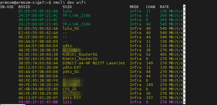
Use the
nmclicommand to connect to the scanned WiFi network:- Replace
wifi_namewith the name of the WiFi hotspot you want to connect to. - Replace
wifi_passwordwith the password for that WiFi hotspot.
root@armsom-cm5:~$ nmcli dev wifi connect "wifi_name" password "wifi_password"
Device 'wlan0' successfully activated with "wlan0b6d10bba-e1d5-4b6d-a17f-7d5ab44bbb6f".- Replace
Use the
ip addr show wlan0command to view the IP address of the WiFi connection.root@armsom-cm5:~$ ip addr show wlan0
4: wlan0: <BROADCAST,MULTICAST,UP,LOWER_UP> mtu 1500 qdisc pfifo_fast state UP group default qlen 1000
link/ether b8:2d:28:5a:52:6a brd ff:ff:ff:ff:ff:ff
inet 192.168.10.9/24 brd 192.168.10.255 scope global dynamic noprefixroute wlan0
valid_lft 86321sec preferred_lft 86321sec
inet6 fe80::850d:3119:e0:afa3/64 scope link noprefixroute
valid_lft forever preferred_lft foreverUse the
pingcommand to test network connectivity over WiFi. You can interrupt the ping command usingCtrl+C.root@armsom-cm5:~$ ping www.baidu.com
PING www.a.shifen.com (183.2.172.185): 56 data bytes
64 bytes from 183.2.172.185: icmp_seq=0 ttl=53 time=8.370 ms
64 bytes from 183.2.172.185: icmp_seq=1 ttl=53 time=8.917 ms
64 bytes from 183.2.172.185: icmp_seq=2 ttl=53 time=8.511 ms
64 bytes from 183.2.172.185: icmp_seq=3 ttl=53 time=8.673 ms
^C
--- www.a.shifen.com ping statistics ---
4 packets transmitted, 4 packets received, 0% packet loss
round-trip min/avg/max/stddev = 8.370/8.618/8.917/0.203 ms
Connect to WiFi using the server image via graphical interface
Log in to the Linux system. You can do this in one of three ways:
- If the CM5 Kit is connected to a network cable, you can remotely log in via SSH.
- If the CM5 Kit is connected to a debug serial port, you can use a serial terminal to log in (use MobaXterm, as Minicom cannot display the graphical interface).
- If the CM5 Kit is connected to an HDMI display, you can log in using the terminal displayed on the HDMI screen.
In the command line, enter the
nmtuicommand to open the WiFi connection interface.
root@armsom-cm5:~$ nmtuiSelect "Activate a connection" and press Enter.
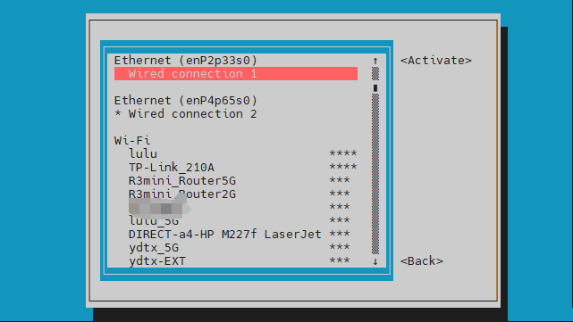
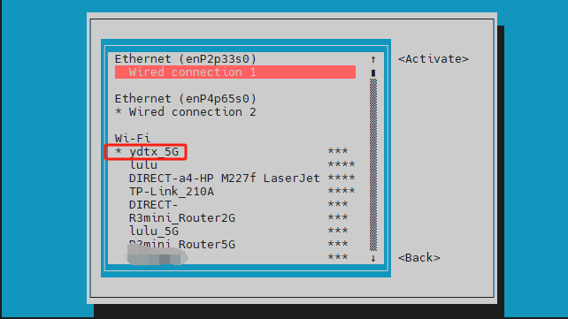
Select the WiFi hotspot you want to connect to and enter the password. Once connected, an asterisk (*) will appear next to the connected WiFi network.
Use the
ip addr show wlan0command to view the WiFi connection's IP address.root@armsom-cm5:~$ ip addr show wlan0
4: wlan0: <BROADCAST,MULTICAST,UP,LOWER_UP> mtu 1500 qdisc pfifo_fast state UP group default qlen 1000
link/ether b8:2d:28:5a:52:6a brd ff:ff:ff:ff:ff:ff
inet 192.168.10.9/24 brd 192.168.10.255 scope global dynamic noprefixroute wlan0
valid_lft 86316sec preferred_lft 86316sec
inet6 fe80::a422:3494:3147:92d/64 scope link noprefixroute
valid_lft forever preferred_lft foreverUse the
pingcommand to test WiFi network connectivity. You can interrupt the ping command usingCtrl+C.root@armsom-cm5:~$ ping www.baidu.com
PING www.a.shifen.com (183.2.172.185): 56 data bytes
64 bytes from 183.2.172.185: icmp_seq=0 ttl=53 time=8.370 ms
64 bytes from 183.2.172.185: icmp_seq=1 ttl=53 time=8.917 ms
64 bytes from 183.2.172.185: icmp_seq=2 ttl=53 time=8.511 ms
64 bytes from 183.2.172.185: icmp_seq=3 ttl=53 time=8.673 ms
^C
--- www.a.shifen.com ping statistics ---
4 packets transmitted, 4 packets received, 0% packet loss
round-trip min/avg/max/stddev = 8.370/8.618/8.917/0.203 ms
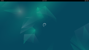
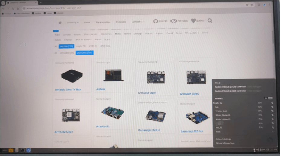
Test method for desktop image
Click the network configuration icon on the desktop (make sure the network cable is disconnected when testing WiFi).
After successfully connecting to WiFi, you can open a browser to check if you can access the internet.
Network Settings Network Settings
Bluetooth
# 1. Activate Bluetooth
root@armsom-cm5:/# service bluetooth start
# 2. Enter bluetoothctl
root@armsom-cm5:/# bluetoothctl
# 3. Enter the following commands to connect
root@armsom-cm5:/# power on
root@armsom-cm5:/# agent on
root@armsom-cm5:/# default-agent
root@armsom-cm5:/# scan on
root@armsom-cm5:/# pair yourDeviceMAC
HDMI
The CM5 Kit supports HDMI up to 4Kp120.
- Use an HDMI cable to connect the CM5 Kit to an HDMI display.
- After booting the Linux system, if the HDMI display has an image output, it indicates that the HDMI interface is working normally.
Note: Many laptops have an HDMI port, but it usually only supports output, not HDMI input. This means it cannot display the HDMI output from other devices on the laptop screen. If you plan to connect the development board's HDMI to a laptop's HDMI port, please first confirm that your laptop supports HDMI input. If HDMI does not display anything, please check if the system you are using has a desktop version, as the server version will only display a terminal.
HDMI to VGA Display Test
You will need the following accessories:
- HDMI to VGA adapter
- A VGA cable and a monitor that supports VGA input
The HDMI to VGA display test is shown below:
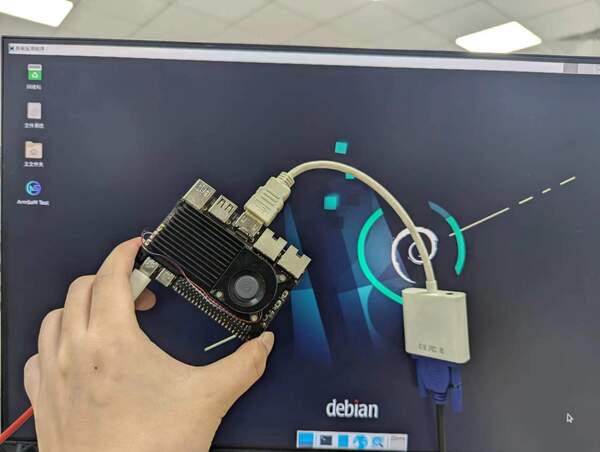
When using HDMI to VGA display, there is no need to configure anything on the CM5 Kit or Linux system. As long as the HDMI interface on the development board displays correctly, it should work. If you encounter issues, please check the HDMI to VGA adapter, VGA cable, and monitor.
USB
USB Mouse or Keyboard Connection Test
- Insert a USB keyboard into the CM5 Kit's USB port.
- Connect the CM5 Kit to an HDMI display.
- If the mouse or keyboard can operate the system normally, it indicates that the USB port is working correctly (the mouse can only be used in a desktop version of the system).
USB Storage Device Connection Test
- Insert a USB flash drive or USB external hard drive into the CM5 Kit's USB port.
- Run the following command. If you see an output for
sdX, it indicates that the USB drive is recognized successfully:
root@armsom-cm5:/# cat /proc/partitions | grep "sd*"
major minor  #blocks  name
   8        0  122880000 sda
- Use the
mountcommand to mount the USB drive to/mnt/, and then you can view the files on the USB drive:
root@armsom-cm5:/# sudo mount /dev/sda1 /test/
- After mounting, use the
df -hcommand to check the USB drive’s capacity and mount point:
root@armsom-cm5:/test# df -h | grep "sd"
/dev/sda        4.7G  4.7G     0  100% /test
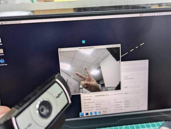
USB Camera
Prepare a USB camera that supports the UVC protocol, then insert the USB camera into the CM5 Kit's USB port.
Use the
v4l2-ctlcommand to see the device node information for the USB camera, which will be/dev/video0:
root@armsom-cm5:/# v4l2-ctl --list-devices
Logitech HD Webcam C93 (usb-xhci-hcd.5.auto-1):
        /dev/video40
        /dev/video41
        /dev/media4
- On a desktop system, you can use Cheese/V4L2 Test Bench to directly open the USB camera:
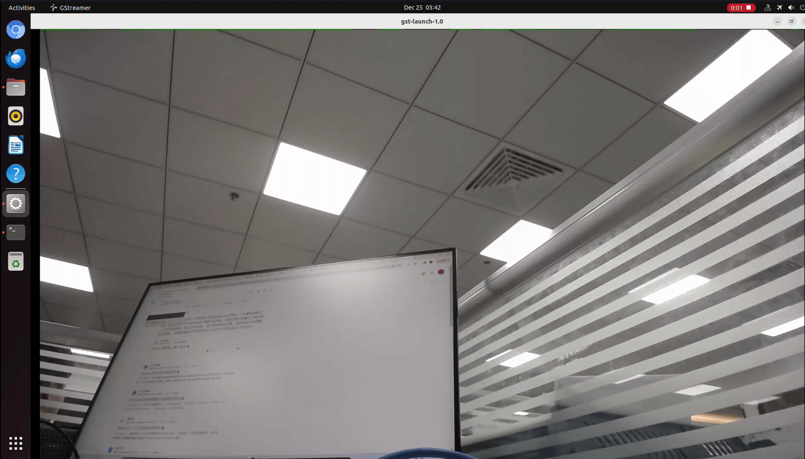
You can also use terminal commands to open the camera preview:
root@armsom-cm5:/# gst-launch-1.0 v4l2src device=/dev/video0 io-mode=4 ! videoconvert ! video/x-raw,format=NV12,width=1920,height=1080 ! xvimagesink;
Command to take a photo:
root@armsom-cm5:/# gst-launch-1.0 v4l2src device=/dev/video0 io-mode=4 ! videoconvert ! video/x-raw,format=NV12,width=1920,height=1080 ! jpegenc ! multifilesink location=/home/armsom/test.jpg;
Command to record a video:
gst-launch-1.0 v4l2src num-buffers=512 device=/dev/video0 io-mode=4 ! videoconvert ! video/x-raw, format=NV12, width=1920, height=1080, framerate=30/1 ! tee name=t ! queue ! mpph264enc ! queue ! h264parse ! mpegtsmux ! filesink location=/home/armsom/test.mp4
M.2 Key M
The CM5 Kit features an M.2 Key M connector:
- On the back of the product, there is an M.2 Key M connector. The board includes a standard M.2 2280 mounting hole for deploying an M.2 2280 NVMe SSD.
Note: This M.2 interface does not support M.2 SATA SSDs.
root@armsom-cm5:/# mkdir temp
root@armsom-cm5:/# mount /dev/nvme0n1 temp
Audio
Check the sound cards in the system.
root@armsom-cm5:/# aplay -l
**** List of PLAYBACK Hardware Devices ****
card 0: rockchipes8388c [rockchip,es8388-codec], device 0: 2a610000.sai-ES8323 HiFi ES8323 HiFi-0 [2a610000.sai-ES8323 HiFi ES8323 HiFi-0]
  Subdevices: 1/1
  Subdevice #0: subdevice #0
card 1: rockchipdp0 [rockchip-dp0], device 0: rockchip-dp0 spdif-hifi-0 [rockchip-dp0 spdif-hifi-0]
  Subdevices: 1/1
  Subdevice #0: subdevice #0
card 2: rockchiphdmi [rockchip-hdmi], device 0: rockchip-hdmi i2s-hifi-0 [rockchip-hdmi i2s-hifi-0]
  Subdevices: 1/1
  Subdevice #0: subdevice #0
Play audio
root@armsom-cm5:/# aplay -D plughw:1,0 ./usr/share/sounds/alsa/Front_Right.wav
FAN
The CM5 Kit comes with a 5V fan using a 0.8mm connector.
The fan has five default states:
| Temperature | State | PWM Speed |
|---|---|---|
| Below 50°C | 0 | 0 |
| 50°C-55°C | 1 | 50 |
| 55°C-60°C | 2 | 100 |
| 60°C-65°C | 3 | 150 |
| 65°C-70°C | 4 | 200 |
| Above 70°C | 5 | 250 |
// Check the current speed
root@armsom-cm5:/# cat /sys/class/hwmon/hwmon9/pwm1
40 PIN
The CM5 Kit provides a 40-PIN GPIO header, compatible with most sensors on the market.
RGB LED
The CM5 Kit has a green LED.
- User Green LED: By default, it remains on to indicate that the system is operating normally.
RTC
- The CM5 Kit is equipped with an RTC IC LK8563S.
- First, insert the RTC battery into the 2-pin header to power the RTC IC.
- Note: The RTC battery should remain in the RTC connector, and confirm that the rtc LK8563S device has been created.
root@armsom-cm5:/# dmesg | grep rtc
[    3.476710] rtc-hym8563 2-0051: rtc information is valid
[    3.488534] rtc-hym8563 2-0051: registered as rtc0
[    3.490109] rtc-hym8563 2-0051: setting system clock to 2024-06-16T09:45:52 UTC (1718531152)
- Locate rtc0, then use the following commands to set the system time and synchronize it with rtc0.
root@armsom-cm5:/# hwclock -r
2023-11-03 10:32:40.461910+00:00
root@armsom-cm5:/# date
2023年 11月 03日 星期五 10:33:12 UTC
root@armsom-cm5:/# hwclock -w
root@armsom-cm5:/# hwclock -r
root@armsom-cm5:/# poweroff
- Remove the RTC battery, wait for 10 minutes or longer, reinsert the RTC battery, and power on Sige7. Check if the RTC is synchronized with the system clock.
root@armsom-cm5:/# hwclock -r
2023-11-03 10:35:40.461910+00:00
root@armsom-cm5:/# date
2023年 11月 03日 星期五 10:36:01 UTC
MIPI-CSI
Basic Commands
// Check the video formats supported by the video node
root@armsom:/# v4l2-ctl -d /dev/video22 --get-fmt-video
Format Video Capture Multiplanar:
        Width/Height      : 2112/1568
        Pixel Format      : 'NV12' (Y/UV 4:2:0)
        Field             : None
        Number of planes  : 1
        Flags             :
        Colorspace        : Default
        Transfer Function : Default
        YCbCr/HSV Encoding: Default
        Quantization      : Full Range
        Plane 0           :
           Bytes per Line : 2112
           Size Image     : 4967424

// Check the topology
root@armsom-cm5:/# media-ctl -d /dev/media2 -p
Using ArmSoM Camera Module 1
The camera uses the camera-module1 module. After connecting and powering the camera module, check the startup logs.
root@armsom-cm5:/# dmesg | grep ov13850
[    2.302905] ov13850 5-0010: driver version: 00.01.05
[    2.302944] ov13850 5-0010: Failed to get power-gpios, maybe no use
[    2.303067] ov13850 5-0010: supply avdd not found, using dummy regulator
[    2.303153] ov13850 5-0010: supply dovdd not found, using dummy regulator
[    2.303186] ov13850 5-0010: supply dvdd not found, using dummy regulator
[    2.303213] ov13850 5-0010: could not get default pinstate
[    2.303220] ov13850 5-0010: could not get sleep pinstate
[    2.308532] ov13850 5-0010: Detected OV00d850 sensor, REVISION 0xb2
[    2.332058] ov13850 5-0010: Consider updating driver ov13850 to match on endpoints
[    2.332084] rockchip-csi2-dphy csi2-dphy0: dphy0 matches m00_b_ov13850 5-0010:bus type 5
Capture an image using v4l2-ctl
// MIPI-CSI1
root@armsom:/# systemctl restart rkaiq_3A.service
root@armsom:/# v4l2-ctl -d /dev/video22 --set-selection=target=crop,top=0,left=0,width=2112,height=1568 --set-fmt-video=width=2112,height=1568,pixelformat=NV12 --stream-mmap=3 --stream-to=/nv12.bin --stream-count=1 --stream-poll
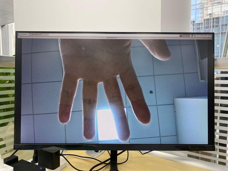
Record video using gst-launch-1.0
// MIPI-CSI1
root@armsom:/# gst-launch-1.0 v4l2src device=/dev/video22 ! video/x-raw,format=NV12,width=2112,height=1568, framerate=30/1 ! xvimagesink
Using Raspberry Pi Camera Module 2
The camera uses the Raspberry Pi Camera Module 2 module. After connecting and powering the camera module, check the startup logs.
root@armsom-cm5:/# dmesg | grep imx219
[    4.049680] imx219 4-0010: driver version: 00.01.02
[    4.074430] imx219 4-0010: Model ID 0x0219, Lot ID 0x258b89, Chip ID 0x056c
[    4.074460] imx219 4-0010: Consider updating driver imx219 to match on endpoints
[    4.074477] rockchip-csi2-dphy csi2-dphy4: dphy4 matches m01_b_imx219 4-0010:bus type 5
Capture an image using v4l2-ctl
root@armsom-cm5:/# v4l2-ctl -d /dev/video11 --set-selection=target=crop,top=0,left=0,width=2112,height=1568 --set-fmt-video=width=1920,height=1080,pixelformat=NV12 --stream-mmap=3 --stream-to=/nv12.bin --stream-count=1 --stream-poll
Record video using gst-launch-1.0
root@armsom-cm5:/# sudo apt-get update
root@armsom-cm5:/# sudo apt-get install gstreamer1.0*
root@armsom-cm5:/# gst-launch-1.0 v4l2src ! 'video/x-raw, format=NV12, width=1920, height=1080' ! autovideosink
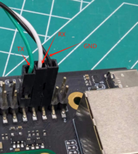
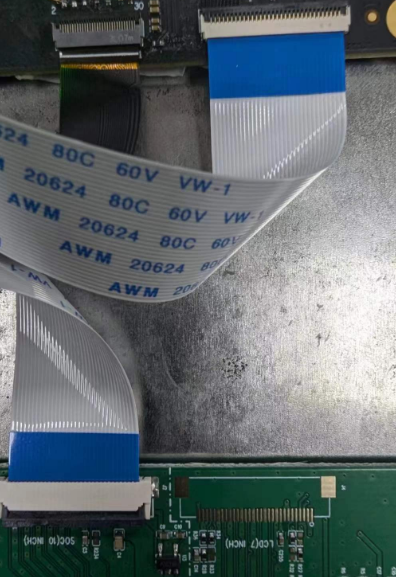
MIPI DSI
The CM5 Kit supports resolutions up to 2K@60Hz.
- Connect the ribbon cable as shown in the image below:
- Configuring a 10.1-inch MIPI LCD screen:
The Linux image does not enable the MIPI LCD screen configuration by default. To use the MIPI LCD screen, you need to enable it manually.
Use
nanoto open the/boot/armbianEnv.txtfile:
sudo nano /boot/armbianEnv.txt
- Find or add the "overlays=" keyword in the file.
// Choose one based on the product you have
overlays=armsom-cm5-io-display-10hd // cm5-kit
overlays=armsom-cm5-rpi-cm4-io-display // cm5-rpi-cm4-io
Shortcut keys: Ctrl + S to save Ctrl + X to exit
// Remount the file system
root@armsom-cm5-io:/home/armsom# sudo mount -o remount
// or
root@armsom-cm5-io:/home/armsom# sync
If you also need to use touch functionality, you will need to load the corresponding driver:
root@armsom-cm5-io:/home/armsom# insmod /usr/lib/modules/6.1.75-vendor-rk35xx/kernel/drivers/input/touchscreen/gt9xx/goodix_gt9xx.ko
Reboot the device to apply the Overlays settings and enable Display 10 HD support.
Purchase Samples
ArmSoM Official Website: https://www.armsom.org/product-page/cm5
ArmSoM Official AliExpress Store: https://aliexpress.com/item/3256807679122184.html
ArmSoM Official Taobao Store: https://item.taobao.com/item.htm?id=842137173767
For OEM & ODM, please contact: sales@armsom.org
What do others say about the CM5?
- itsfoss ArmSoM-CM5:ArmSoM CM5 Powerful Replacement for Raspberry Pi CM4
- Technically Unsure: ArmSoM CM5 | Can it Beat the Raspberry Pi CM5?
Notes
- Before handling the device, please ensure you wear an anti-static wrist strap or take electrostatic discharge measures to prevent damage to the development board.
- Assembly should be performed in an electrostatic-safe environment, avoiding operations in dry and low-humidity conditions.
- When not in use, store the device in an anti-static bag and keep it in a suitably temperature-controlled, low-humidity environment to prevent static electricity buildup.
- When handling the device, avoid friction or collisions to prevent the generation of static electricity that could cause damage.
- When holding the device, try to avoid direct contact with the chips on the mainboard to prevent static damage.
- Do not plug or unplug wires or other devices while the device is operating to avoid damage from electrical surges.
- When connecting or disconnecting the GPIO/MIPI expansion interfaces, make sure to turn off the power and disconnect the power cable to prevent damage from electrical current.
Without effective cooling measures, the surface temperature of the main chip may exceed 60 degrees. When handling the device, please avoid direct contact with the SoC and surrounding power inductors to prevent burns. Ensure that the environment is well-ventilated during operation to prevent localized heat buildup, which could lead to overheating. Additionally, do not place the device in direct sunlight. It is recommended to choose between the official cooling fan, heat sink, or third-party cooling kits based on specific usage conditions to ensure optimal cooling performance.