ArmSoM Dedicated Heatsinks
1. Introduction
ArmSoM board-specific heatsinks combine a finned heatsink with an axial fan. The base transfers heat from the chip to the fins, while airflow carries heat away during sustained workloads such as compilation, AI inference and multimedia processing.
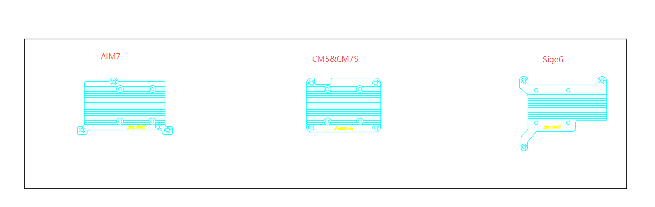
Three variants match the mechanical layouts of AIM7, CM5/CM7S and Sige6. Select a variant by checking the board model, mounting holes, thermal contact area and fan power connector.
2. Selection and Specifications
| Variant | Compatible products | Visual identification | Mechanical files |
|---|---|---|---|
| AIM7 | AIM7 | Shaped mounting tabs, with the fan on one side of the fins | AIM7 V1.1 DXF |
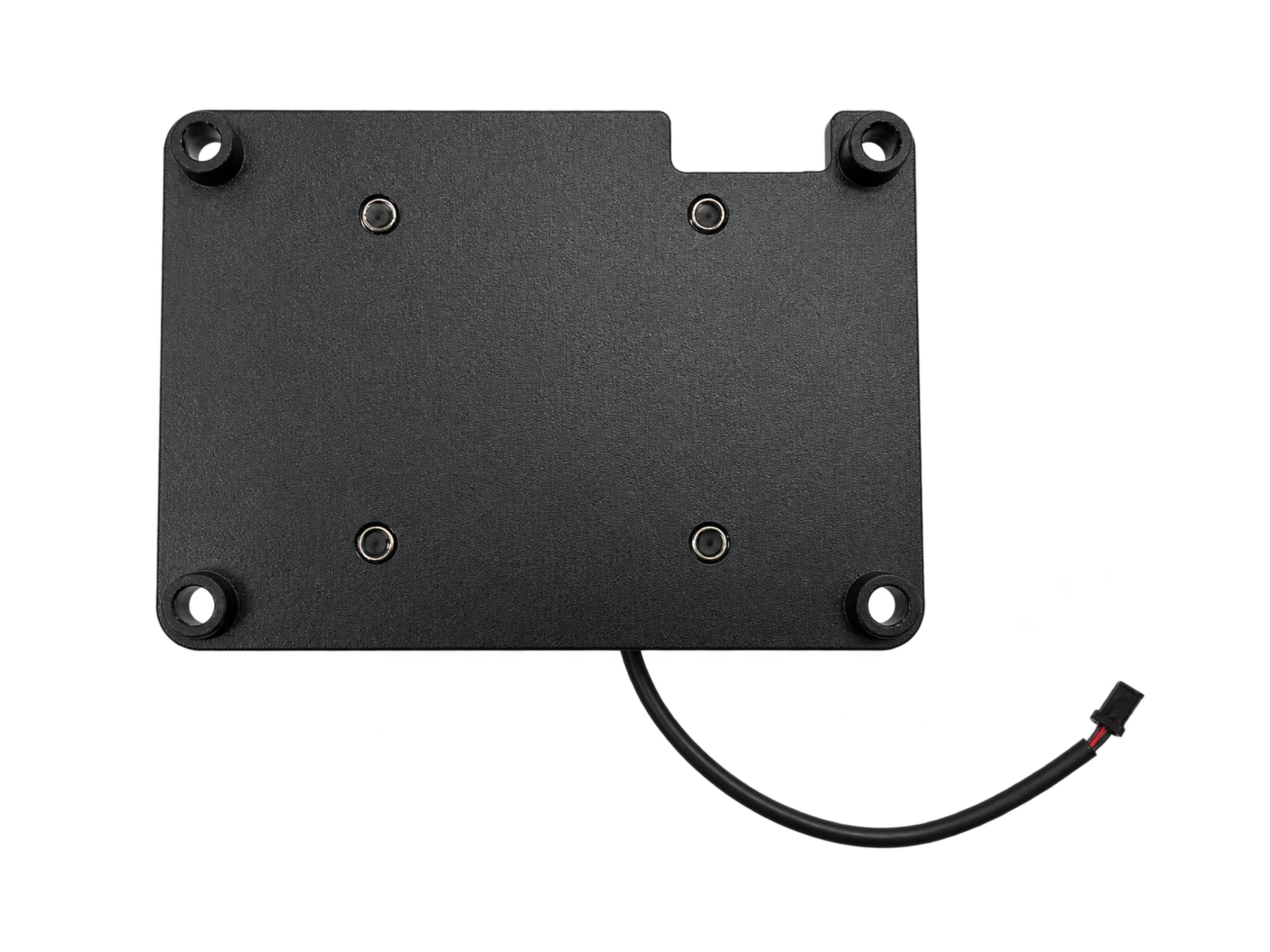
| CM5/CM7S | CM5, CM7S | Rectangular body with mounting holes at the four corners | CM5/CM7S V1.1 DXF |
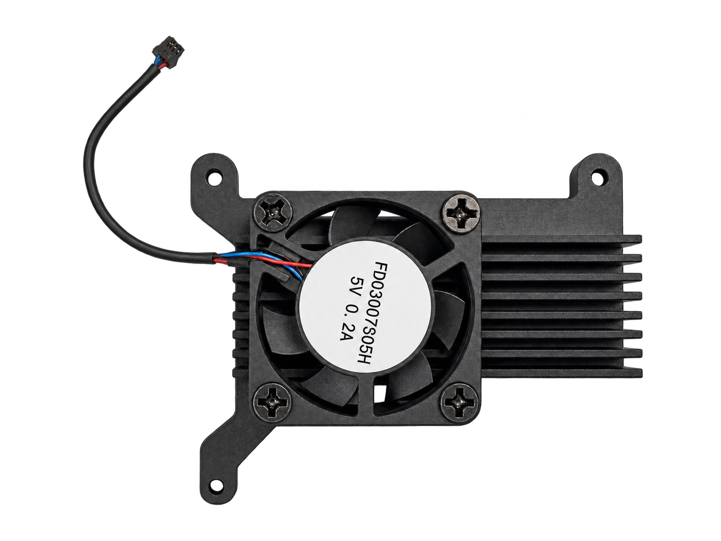
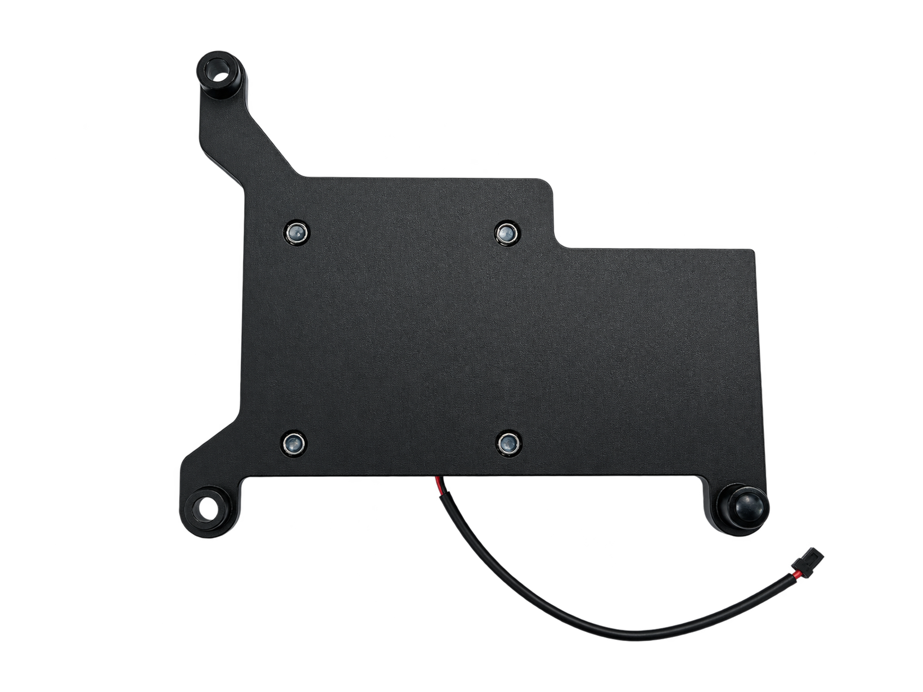
| Sige6 | Sige6 | Asymmetric outline with extended mounting tabs | Outline and product photos below |
| Item | Details |
|---|---|
| Cooling assembly | Black finned heatsink with an axial fan |
| Fan model | FD03007S05H |
| Fan label ratings | DC 5V, 0.2A |
| Connection | Cable and connector; must match the FAN interface on the board or carrier |
| Mounting | Fasten at the matching holes and fit a suitable thermal pad between the chip and heatsink base |
The fan model, voltage and current are taken from the photographed samples. Check the label and supplied specifications for your production batch.
AIM7, CM5 and CM7S are compute modules. Also check clearance on the carrier board and inside the enclosure. Matching mounting holes do not imply matching fan connector pinouts; consult the relevant product documentation before wiring.
3. Product Views
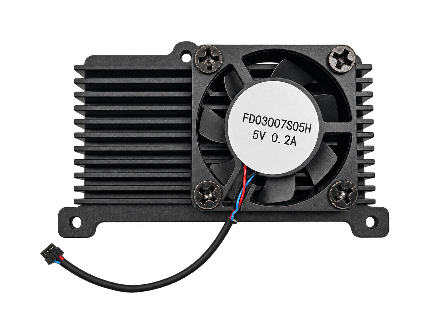
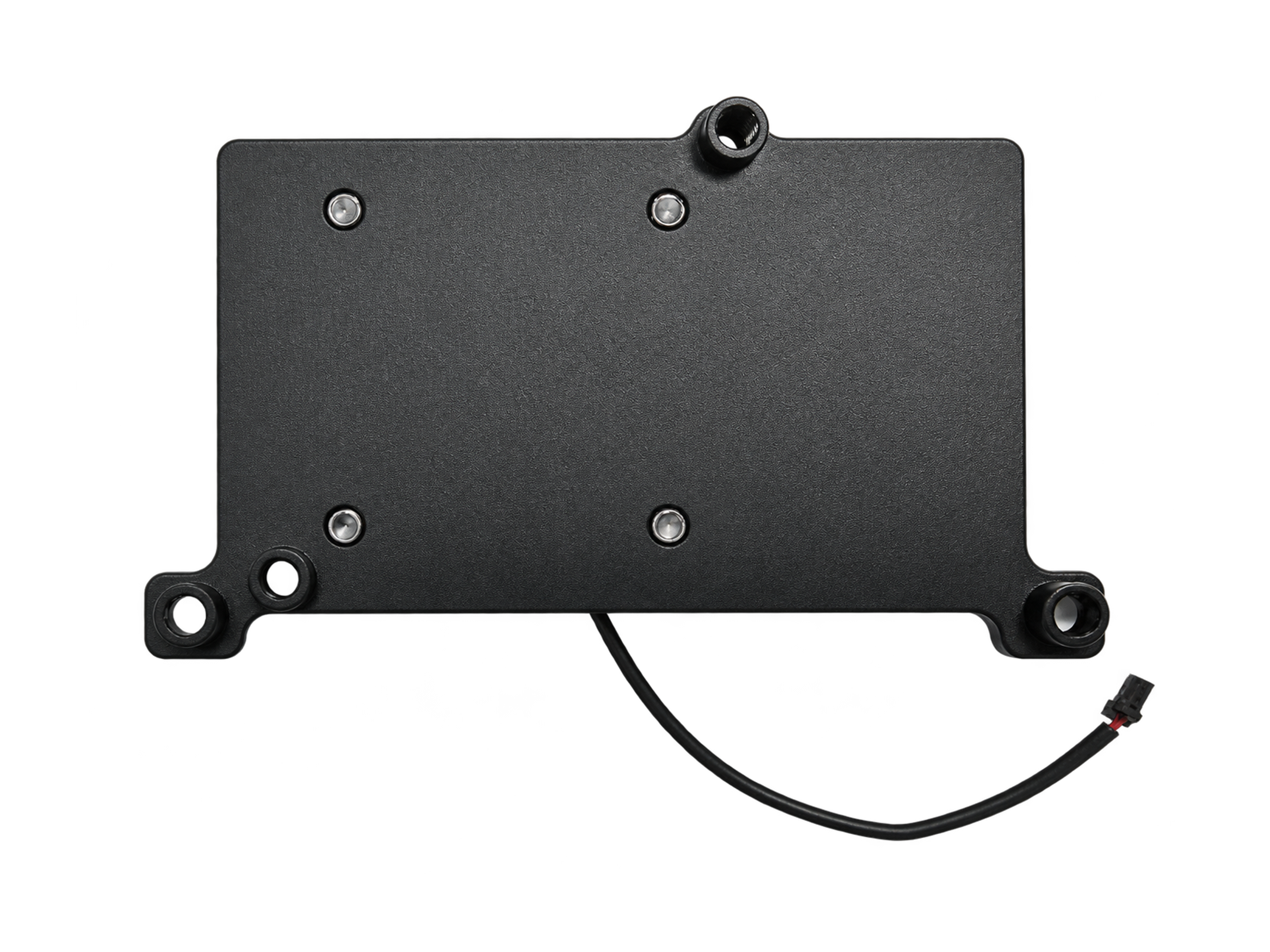
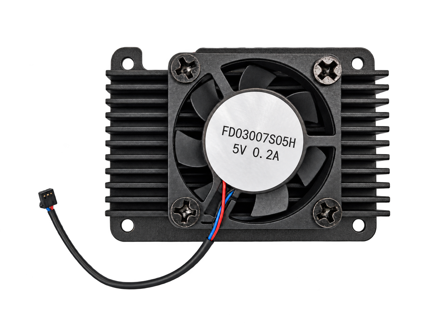
Click a photo to open the larger image. The front shows the fan, fins and cable; the rear shows the mounting points and thermal contact base.
3.1 AIM7 Variant
For ArmSoM AIM7.
3.2 CM5/CM7S Variant
For ArmSoM CM5 and ArmSoM CM7S. Both modules use this heatsink variant.
3.3 Sige6 Variant
For ArmSoM Sige6.
4. Installation and Use
- Shut down and disconnect power. Align the heatsink with the mounting holes and check that it clears connectors and nearby components.
- Place a thermal pad suited to the contact gap between the chip and heatsink base. Remove its protective film before assembly.
- Use fasteners suited to the holes and assembly height, tightening evenly. Check thermal contact, ensure the board is not bent, and keep the cable clear of the fan blades.
- Verify the voltage and pinout of the board or carrier's FAN interface, connect the fan, then restore power.
- Run your application and check fan operation, airflow and chip temperature. With temperature-controlled images, the fan may stop at low temperatures.
Disconnect power before installation or unplugging the fan. Do not identify power, GND or PWM by wire color alone, and do not force incompatible connectors. Overlong screws or an unsuitable thermal pad thickness can cause interference, board bending or poor contact.
For connector locations and control methods, see the AIM7, CM5, CM7S and Sige6 product guides, and the fan interface guide.
5. Mechanical Drawings
| Variant | File | Format / version |
|---|---|---|
| AIM7 | Download the AIM7 heatsink drawing | DXF / V1.1 |
| CM5/CM7S | Download the CM5/CM7S heatsink drawing | DXF / V1.1 |
Open the files in CAD software that supports DXF. Check the outlines, mounting holes and drawing annotations before designing an assembly. Outline and product photos are currently provided for Sige6; contact the address below to inquire about its mechanical file.
6. Purchasing and Inquiries
For samples, matching thermal pads and fasteners, volume orders or mechanical documentation, contact sales@armsom.org.
Specify the AIM7, CM5/CM7S or Sige6 variant, together with your carrier board, enclosure and required quantity, so the matching configuration can be confirmed.