Product Introduction: Sige6
Let's get to know Sige6 in 5 minutes.
Introduction
The ArmSoM-Sige6 is powered by the Allwinner A733 octa-core processor, featuring a high-performance architecture with a dual-core Arm Cortex-A76 and a hexa-core Arm Cortex-A55 (big.LITTLE configuration). Built on a 12nm process with a peak frequency of 2.0GHz, it integrates a 3 TOPS NPU and an Imagination BXM-4-64 MC1 GPU to deliver robust AI and multimedia processing capabilities.
It is ideal for ARM PCs, edge computing, cloud servers, artificial intelligence, cloud computing, VR/AR, blockchain, and intelligent NVR applications.

Key Specifications
- SoC: Allwinner A733-HN3
- CPU: Dual-core Cortex-A76 @ 2.0GHz + Hexa-core Cortex-A55 @ 1.8GHz (12nm process)
- GPU: Imagination BXM-4-64 MC1; supports OpenGL ES 3.2, Vulkan 1.3, and OpenCL 3.0
- NPU: 3 TOPS AI acceleration engine
- VPU / Codec:
- Hardware Decoding: H.265/VP9/AVS2 up to 4K@60fps, H.264 up to 4K@30fps
- Hardware Encoding: H.264/H.265 up to 4K@30fps
- RAM: 2GB/4GB/6GB/8GB/12GB/16GB LPDDR5 (supports up to 16GB)
- Flash: 32GB/64GB/128GB eMMC, reserve SPI flash, not mounted by default
- WIFI/BT: Onboard Wi-Fi 6 + BT 5.4
- Operating Voltage: 5V (±5% voltage tolerance)
- Operating Temperature: -25℃ ~ 115℃
- Operating Systems:
- Official Support: Debian Linux, Android 13
- Third-party Support: Armbian
- PCB: 8-layer through-hole PCB design
- Weight: 47.2g
- Dimensions: 89mm x 56mm x 21.6mm
Getting started
Sige6 User Manual
How to get started with your Sige6
Hardware
Hardware Interface
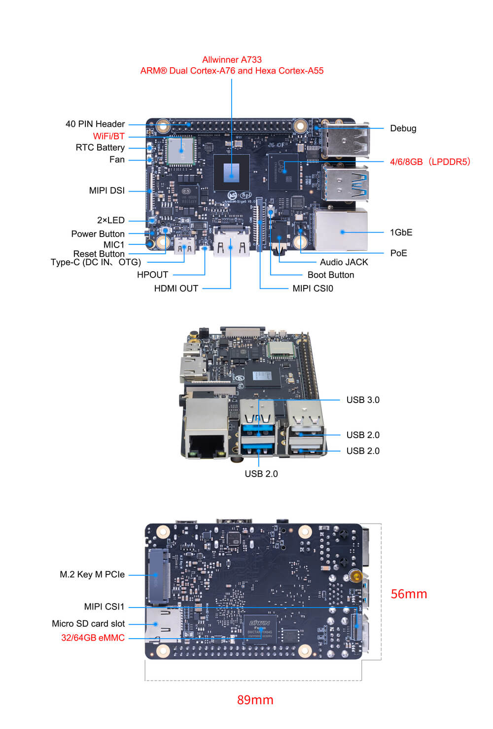
Hardware Spec
Sige6 Hardware Specifications
| Category | Functional Parameters |
|---|---|
| SoC | |
| CPU | |
| GPU | |
| NPU | |
| VPU/Codec | |
| RAM | |
| Flash | |
| PCIe | |
| Networking | |
| Video Output | |
| Video Input | |
| Audio | |
| USB Ports | |
| 40-PIN Header | |
| Other | |
| Power Supply | |
| Buttons | |
| System | |
| Dimensions | |
| Operating Temperature |
Comparison Table of Mainstream Single Board Computers (SBCs) Based on the A733 SoC
| Category | ArmSoM-Sige6 | Orange Pi 4 Pro | Radxa Cubie A7A |
|---|---|---|---|
| SoC | Allwinner A733 | Allwinner A733 | Allwinner A733 |
| CPU Architecture | Dual-core Cortex-A76@2.0GHz + Hexa-core Cortex-A55@1.8GHz | Dual-core Cortex-A76@2.0GHz + Hexa-core Cortex-A55@1.8GHz | Dual-core Cortex-A76@2.0GHz + Hexa-core Cortex-A55@1.8GHz |
| GPU / NPU | BXM-4-64 / 3 TOPS | BXM-4-64 / 3 TOPS | BXM-4-64 / 3 TOPS |
| RAM (LPDDR5) | 2GB/4GB/6GB/8GB/12GB/16GB (Up to 16GB) | Up to 16GB supported | 2GB / 4GB / 6GB / 8GB / 12GB / 16GB |
| Storage (eMMC) | 16GB/32GB/64GB/128GB optional | 16GB/32GB/64GB/128GB optional | 16GB/32GB/64GB/128GB optional |
| Onboard Flash (SPI) | 64Mb (Default), 128Mb, 256Mb optional | 128Mb (Default) / 256Mb optional | 8MB SPI NOR Flash |
| High-speed M.2 | 1x M.2 Key M (PCIe 3.0 2-lanes) | 1x M.2 Key M (PCIe 3.0 2-lanes) | 1x M.2 Key M (PCIe 3.0 1-lane) |
| Ethernet | 1x Gigabit (PoE supported via external HAT) | 1x Gigabit (PoE supported via external HAT) | 1x Gigabit (PoE supported via external HAT) |
| Wireless | Wi-Fi 6, BT 5.0 (External antenna) | Wi-Fi 6 + BT 5.4 (External antenna) | Wi-Fi 6, BT 5.4 (External antenna) |
| Video Output | HDMI 2.0 (4K@60fps) | HDMI 2.0 (4K@60fps) | HDMI 2.0 (4K@60fps) |
| MIPI DSI | 1x 4-lane MIPI DSI | 1x 4-lane MIPI DSI | 1x 4-lane MIPI DSI |
| Camera (CSI) | 1x 2-lane + 1x 4-lane MIPI CSI | 1x 2-lane + 1x 4-lane MIPI CSI | 1x 4-lane or 2x 2-lane MIPI CSI |
| USB Interfaces | 1x USB 3.1, 1x USB 2.0, 1x Type-C OTG | 1x USB 3.0, 3x USB 2.0 | 1x USB 3.1, 3x USB 2.0, 1x Type-C OTG |
| Audio | Audio Jack + HP-OUT | Audio Jack | Audio Jack (Stereo) |
| Expansion | 40-Pin Standard Header | 40-Pin Standard Header | 40-Pin Standard Header |
| Power Input | USB Type-C 5V / PoE / GPIO 5V | USB Type-C 5V / PoE / GPIO 5V | USB Type-C 5V / PoE / GPIO 5V |
| Dimensions | 89mm * 56mm | 89mm * 56mm | 89mm * 56mm |
| OS Support | Debian, Android 13 | Ubuntu, Debian, Android 13 | Debian, Android 13 |
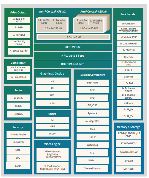
Allwinner a733 Diagram
Allwinner a733 Diagram
Hardware Pin Definitions
40-PIN header
| GPIO number | function | Pin | Pin | function | GPIO number |
|---|---|---|---|---|---|
| +3.3V | 1 | 2 | +5.0V | ||
| 313 | PJ25/PWM1-7/UART4-RX/TWI4-SDA/SPI3-MOS | 3 | 4 | +5.0V | |
| 312 | PJ24/PWM1-6/UART4-TX/TWI4-SCK/SPI3-CLK | 5 | 6 | GND | |
| 356 | PL4/S-TWI2-SCK/S-PWM0-2 | 7 | 8 | PL2/S-UART1-TX/S-UART0-TX/S-TWI1-SDA/S-PWM0-0 | 354 |
| GND | 9 | 10 | PL3/S-UART1-RX/S-UART0-RX/S-TWI1-SCK/S-IR-RX/S-PWM0-1 | 355 | |
| 357 | PL5/S-TWI2-SDA/S-SPI0-CLK/S-PWM0-3 | 11 | 12 | PK0//UART6-DCD/I2S4-BCLK | 320 |
| 358 | PL6/S-UART0-TX/S-SPI0-MOSI/S-IR-RX/S-PWM0-4 | 13 | 14 | GND | |
| 359 | PL7/S-UART0-RX/S-SPI0-MISO/S-PWM0-5 | 15 | 16 | PB0/UART2-TX/UART0-TX/SPI2-CS0 | 32 |
| +3.3V | 17 | 18 | PB1/UART2-RX/UART0-RX/SPI2-CLK | 33 | |
| 108 | PD12/SPI1-MOS | 19 | 20 | GND | |
| 109 | PD13/SPI1-MISO | 21 | 22 | PK6/TWI2-SCK/UART4-TX/UART2-RTS/SPI3-MOSI | 326 |
| 107 | PD11/SPI1-CLK | 23 | 24 | PD10/SPI1-CS0/PWM1-0 | 106 |
| GND | 25 | 26 | PD15/SPI1-CS1/UART3-CTS | 111 | |
| 315 | PJ27/PWM1-9/UART4-CTS/UART2-RX/TWI5-SDA | 27 | 28 | PJ26/PWM1-8/UART4-RTS/UART2-TX/TWI5-SCK/SPI3-MISO | 314 |
| 362 | PL10/S-UART0-TX/S-TWI2-SCK/S-UART1-TX/S-PWM0-8/ | 29 | 30 | GND | |
| 321 | PK1/UART6-DSR/I2S4-MCLK/TWI1-SCK | 31 | 32 | PL9/S-TWI1-SDA/S-UART1-RX/S-TWI0-SDA/S-TWI2-SDA/S-PWM0-7 | 361 |
| 360 | PL8/S-TWI1-SCK/S-UART1-TX/S-TWI0-SCK/S-TWI2-SCK/S-PWM0-6 | 33 | 34 | GND | |
| 322 | PK2/UART6-DTR/I2S4-LRCK/HDMI-SDA/TWI5-SDA | 35 | 36 | PD14/LCD0-D20/SPI1-HOLD/UART3-RTS | 110 |
| 325 | PK5/PWM1-8/PWM1-9/SPI3-CLK | 37 | 38 | PK4/I2S4-DOUT0/I2S4-DIN1 | 324 |
| GND | 39 | 40 | PK3/UART6-RI/I2S4-DIN0/I2S4-DOUT1/TWI5-SCK | 323 |
Resources
Source Code
How to obtain the SDK:
jackson@armsom:~$ git clone https://cnb.cool/armsom-2025/T527_AIOT_V1.4.8
SDK construction method:
- Before compiling SDK, you need to configure the relevant information as follows
jackson@armsom:~/T527_AIOT_V1.4.8$ ./build.sh config
========ACTION List: mk_config ;========
options :
All available platform: //Choose a Linux system
   0. android
   1. linux
Choice [linux]: 1
All available linux_dev: //Choose the OS you need
   0. bsp
   1. dragonboard
   2. buildroot
   3. debian
   4. yocto
Choice [debian]: 3
All available kern_name: //Select the kernel version, currently only 5.15 is supported
   0. linux-5.10
   1. linux-5.15
   2. linux-6.6
Choice [linux-5.15]: 1
All available ic: //Choose the chip platform you need
   0. a523
   1. a527
   2. a733
   3. t527
   4. t736
Choice [a733]: 2
All available board: //Choose the board card plan you need
   0. QA
   1. armsom_sige6
   2. cubie_a7a
   3. cubie_a7z
   4. evb1
   5. fpga
   6. perf1
   7. pro2
   8. pro3
Choice [armsom_sige6]: 1
All available flash: //Choose the storage media you need
   0. default
   1. nor
Choice [default]: 0
All available rootfs files: //Choose the system version you need
   0. linaro-bullseye-gnome-arm64.tar.gz
   1. linaro-bullseye-xfce-arm64.tar.gz
   2. linaro-bullseye-xfce-ros2-humble-arm64.tar.gz
Choice [linaro-bullseye-gnome-arm64.tar.gz]: 0
Setup BSP files
- After configuring the relevant information, start compiling the SDK
jackson@armsom:~/T527_AIOT_V1.4.8$ ./build.sh
- After compiling the SDK, package the image
jackson@armsom:~/T527_AIOT_V1.4.8$ ./build.sh pack
Firmware generation path: ~/T527_AIOT_V1.4.8/out/a733_linux_armsom_sige6_uart0.img
How to compile a specific partition on its own
1.Compile U‑boot
jackson@armsom:~/T527_AIOT_V1.4.8$ ./build.sh bootloader
2.Compile Kernel
jackson@armsom:~/T527_AIOT_V1.4.8$ ./build.sh kernel
3.Compile Debian
jackson@armsom:~/T527_AIOT_V1.4.8$ ./build.sh debian_rootfs
4.Compile Buildroot
jackson@armsom:~/T527_AIOT_V1.4.8$ ./build.sh buildroot_rootfs
Cloud drive link
Google Drive links in general, including software materials and hardware materials
Official mirror
ArmSoM team uses Debian bullseye as the official operating system.How to Flash Image📤
The following systems have been tested and verified by ArmSoM official:
| logo | Description | Cloud drive path |
|---|---|---|
 | debian11 for Sige6 : Debian 11 (Bullseye) is a stable, free, open-source Linux distro, with a long-term support kernel and over 59,000 software packages. | software → Debianfirmware |
Third Party System
| logo | Description | Download |
|---|
Hardware Resources
Get the Sige6 schematics, DXF, and other hardware files. Cloud drive path: ArmSoM-Sige6 → hardware Files
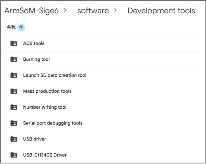
Development tools
Get tools for ADB debugging, flashing, serial ports, and SD card creation. Cloud drive path: ArmSoM-Sige6 → software → Development tools
User Manual
1. Preparation for getting started
Before starting to use ArmSoM-Sige products, please prepare the following items
Tools ready
- Power supply
- System Installation (Choose One)
- Onboard eMMC startup
- USB Type-C data cable, to write an image from the Type-C port on the Sige series, you need a Type-C data cable to connect the Sige series and the PC. MicroSD card/TF card boot
- MicroSD card/TF card boots
- MicroSD card/TF card, Class 10 or above, at least 8GB SDHC, and card reader
- Here are the high-speed TF cards tested and verified by the ArmSoM team
- SanDisk 32GB TF (MicroSD) Dashcam & Security Monitoring Dedicated Storage Card (Recommended for Long-Term Operation)
- SanDisk 32GB TF (MicroSD) Storage Card for Dashcams & Security Monitoring (Recommended for Long-Term Use)
- SanDisk TF 8GB Class10 microSD
- SanDisk TF 128G Class10 microSD XC TF 128G 48MB/S:
- Onboard eMMC startup
You can set Sige as a desktop interactive computer, or you can set it as a headless computer that can only be accessed through the network. To set Sige as a headless computer, you configure the hostname, user accounts, network connections, and SSH during the initial installation of the operating system. If you want to use Sige directly, you will need the following additional accessories:
Optional options
- Keyboard & Mouse
- HDMI monitor and HDMI cable
- Ethernet cable (network cable)
- Camera module
- It is recommended to use camera-module1 module.
- LCD display
- Display 10 HDis recommended.
- Audio cable, 0.8mm vertical socket.
- RTC battery, 0.8mm vertical socket.
- Fan, 0.8mm vertical socket.
Power supply
The table below shows the power specifications required to power the ArmSoM-Sige6. You can use any high-quality power supply that provides the correct power mode.
| Model | Recommended Power Supply (Voltage/Current) | Power supply mode |
|---|---|---|
| Sige6 | 5V/3A | USB Type-C |
Plug the power into the port labeled "PWR IN", and make sure to use the correct port!
Account needed to log in
| Username | Password |
|---|---|
| root | root |
2. Programming method selection
2.1 Flashing tools
| tools | Operating system | Description |
|---|---|---|
| PhoenixSuit | windows | Partition upgrade and full firmware upgrade tool |
| PhoenixCard | windows | SD Card Firmware Tool |
| PhoenixUSBpro | windows | Mass production upgrade tool, supports USB one-to-eight programming |
2.2 Burning method
There are two ways to flash: using a USB cable to flash to eMMC or using a card reader to flash to MicroSD. You can choose either one.
2.2.1 Burning to eMMC via USB cable
Flashing an image to the eMMC requires using the PhoenixSuit flashing tool and the USB driver (InstallUSBDrv.bat)
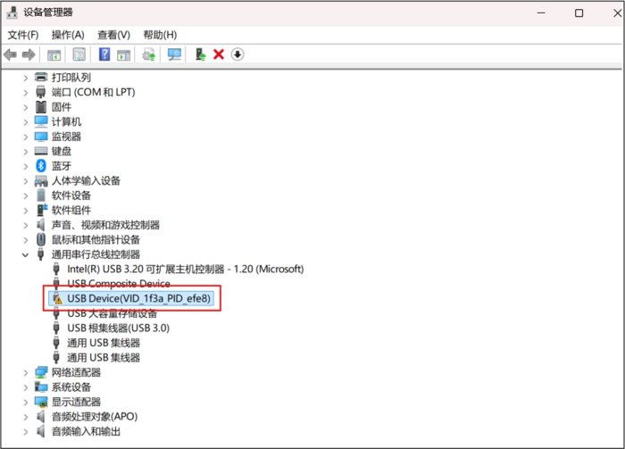
First, install the USB driver by double-clicking and running InstallUSBDrv.bat.
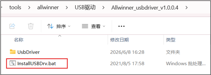
After installing the USB driver, you can open Device Manager in Windows and see the USB Device (VID_1f3a_PID_efe8) listed.
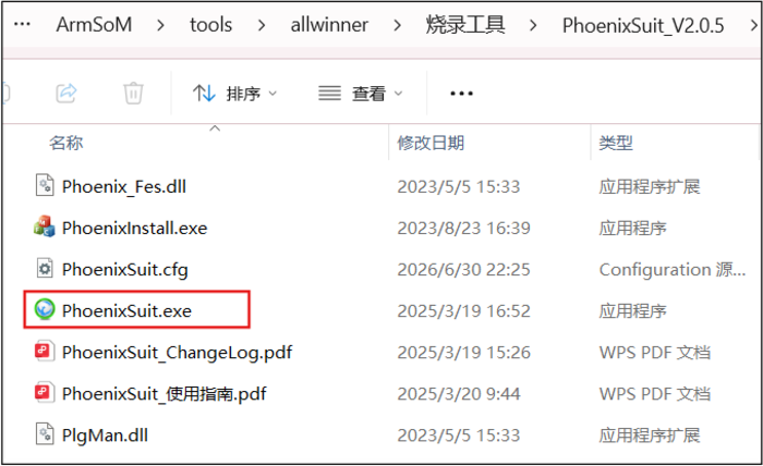
Next, open the flashing tool (run PhoenixSuit.exe)
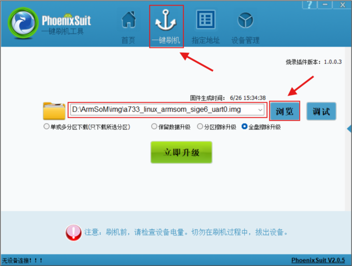
Click 'One-Click Flash', then click 'Browse' and choose the firmware path you want to flash
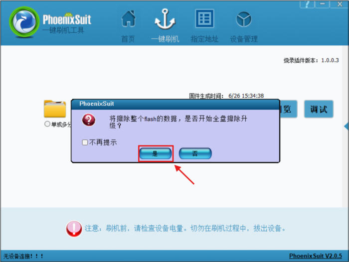
Hold down the Recovery button on the development board, then power on the board until PhoenixSuit pops up with 'This will erase all data on the flash. Do you want to start a full erase and upgrade?' Then just click Yes and wait for the firmware to finish burning.
2.2.2 Program the card reader to MiroSD
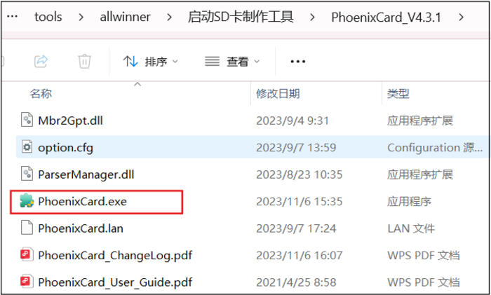
- Open the bootable SD card creation tool and double-click PhoenixCard.exe to run it.
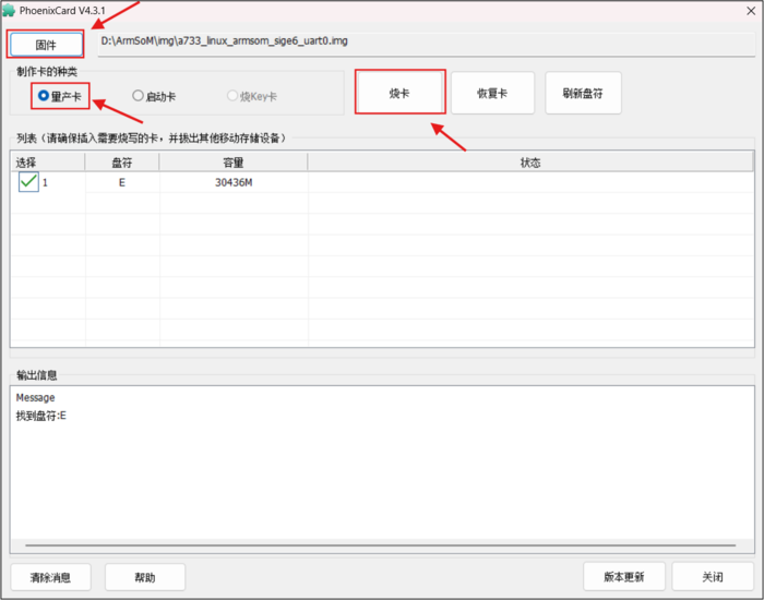
- Click on the firmware, choose the firmware path you want to flash; check 'Mass Production Card', and then just click 'Burn Card'.
- Insert the prepared SD card into the development board's TF card slot, and power on the board to boot from the SD card.
3. Interface usage
If this is your first time using the ArmSoM-Sige6 product, please get familiar with the product's hardware interfaces first so you can better understand the content that follows.
| Hardware interfaces | Sige6 |
|---|
3.1 Debugging the serial port
Connect the USB to TTL serial cable to the socket marked "Debug" on the baseboard as shown below:
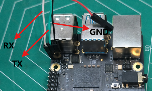
| Sige6 | Connection | Serial port module |
|---|---|---|
| GND | ---> | GND |
| TX | ---> | RX |
| RX | ---> | TX |
Serial communication parameters
- Port rate: 115200
- Data bits: 8
- Stop position: 1
- Checksum bits: None
- Flow control: None
3.2 Ethernet Port
- First, plug one end of the network cable into the ArmSoM-Sige6 Ethernet port, connect the other end to the router, and make sure to do so The internet is unobstructed
- After system startup, it automatically assigns an IP address to the Ethernet card via DHCP, requiring no additional configuration
- The command to view IP addresses in the ArmSoM-Sige6 Linux system is as follows, where eth0 is the name of the Ethernet card device
root@localhost:~# ip a
1: lo: <LOOPBACK,UP,LOWER_UP> mtu 65536 qdisc noqueue state UNKNOWN group default qlen 1000
    link/loopback 00:00:00:00:00:00 brd 00:00:00:00:00:00
    inet 127.0.0.1/8 scope host lo
       valid_lft forever preferred_lft forever
    inet6 ::1/128 scope host
       valid_lft forever preferred_lft forever
2: sit0@NONE: <NOARP> mtu 1480 qdisc noop state DOWN group default qlen 1000
    link/sit 0.0.0.0 brd 0.0.0.0
3: eth0: <BROADCAST,MULTICAST,UP,LOWER_UP> mtu 1500 qdisc mq state UP group default qlen 1000
    link/ether 60:f1:6b:3a:2b:fc brd ff:ff:ff:ff:ff:ff
    inet 192.168.1.181/24 brd 192.168.1.255 scope global dynamic noprefixroute eth0
       valid_lft 43198sec preferred_lft 43198sec
    inet6 fd85:d322:c276:0:a827:46f6:9747:d4b1/64 scope global noprefixroute
       valid_lft forever preferred_lft forever
    inet6 fe80::7a4f:2a6b:3dcd:6d6a/64 scope link noprefixroute
       valid_lft forever preferred_lft forever
4: wlan0: <NO-CARRIER,BROADCAST,MULTICAST,UP> mtu 1500 qdisc mq state DOWN group default qlen 1000
    link/ether 66:03:a5:e0:d5:da brd ff:ff:ff:ff:ff:ff permaddr f0:bf:bc:f6:3a:8e
There are three ways to check the IP address after ArmSoM-Sige6 starts:
- Connect to the HDMI monitor, then log into the system and use the terminal to enter the ip a command to check the IP address
- Connect to the debug serial port terminal and enter the ip a command to check the IP address
- If there is no debug serial port and no HDMI display, you can also check the IP address of the ArmSoM-Sige6 port through the router's management interface. However, this method often causes people to fail to properly see the ArmSoM-Sige6 IP address. If you can't see it, the debugging method is as follows:
- First, check if the Linux system has started up normally. If the ArmSoM-SigeX green light stays on, it usually starts normally. If only the red light is on, it means the system hasn't started properly.
- Check if the network cable is securely plugged in, or try replacing the cable.
- Try switching routers. I've encountered many issues, such as the router not assigning IP addresses properly, or the IP addresses that have been assigned correctly but are not visible in the router.
- If you don't have a router to replace, you can only connect an HDMI monitor or use a debug serial port to check the IP address.
Additionally, note that ArmSoM-Sige6 DHCP automatically allocates IP addresses without any setup.
- Use the ping tool to check if the network is connected.
The command to test network connectivity is as follows. The ping command can be interrupted by pressing the Ctrl+C shortcut
root@localhost:~# ping -I eth0 www.baidu.com
PING www.a.shifen.com (103.235.46.115) from 192.168.1.181 eth0: 56(84) bytes of data.
64 bytes from 103.235.46.115 (103.235.46.115): icmp_seq=3 ttl=47 time=160 ms
64 bytes from 103.235.46.115 (103.235.46.115): icmp_seq=4 ttl=47 time=171 ms
64 bytes from 103.235.46.115 (103.235.46.115): icmp_seq=5 ttl=47 time=159 ms
64 bytes from 103.235.46.115 (103.235.46.115): icmp_seq=6 ttl=47 time=154 ms
^C
--- www.a.shifen.com ping statistics ---
6 packets transmitted, 4 received, 33.3333% packet loss, time 5055ms
rtt min/avg/max/mdev = 153.526/160.843/170.917/6.311 ms
3.3 WIFI
All ArmSoM-Sige series products are onboard WIFI modules, do not require external network ports, and usestandard 4th generation antennas
The server version mirror connects to WiFi via command
- First, log in to the Linux system. There are three ways to do this
- If ArmSoM-SigeX is connected to a network cable, you can remotely log in to the Linux system via SSH
- If ArmSoM-SigeX is connected to the debugging serial port, you can log in to the Linux system using the serial terminal port
- If you connect ArmSoM-SigeX to an HDMI monitor, you can log in to Linux via the HDMI display terminal System
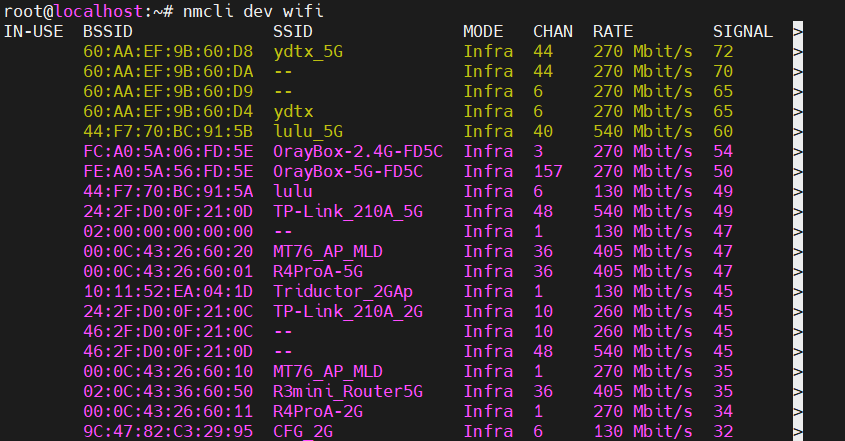
- Use the nmcli dev wifi command to scan nearby WIFI hotspots
# 1. Open the WIFI
root@localhost: nmcli r wifi on
# 2. Scan WIFI
root@localhost: nmcli dev wifi
# 3. Connect to WIFI network
root@localhost: nmcli dev wifi connect "wifi_name" password "wifi_password"
- Use the nmcli command to connect to the scanned WIFI
- wifi_name Change the name of the WiFi hotspot you want to connect to
- wifi_passwd Change the password to the WiFi hotspot you want to connect to
root@localhost:~$ nmcli dev wifi connect "wifi_name" password "wifi_passwd"
Device 'wlan0' successfully activated with '6f6c5ce0-7fd3-4ff7-a72f-94a2424600f3'.
- You can view the WiFi IP address using the ip addr show wlan0 command
root@localhost:~# ip addr show wlan0
4: wlan0: <BROADCAST,MULTICAST,UP,LOWER_UP> mtu 1500 qdisc mq state UP group default qlen 1000
    link/ether f0:bf:bc:f6:3a:8e brd ff:ff:ff:ff:ff:ff
    inet 192.168.1.239/24 brd 192.168.1.255 scope global dynamic noprefixroute wlan0
       valid_lft 43081sec preferred_lft 43081sec
    inet6 fd85:d322:c276:0:50f8:7f68:84ea:2d9d/64 scope global noprefixroute
       valid_lft forever preferred_lft forever
    inet6 fe80::ad1f:8848:5dda:9c06/64 scope link noprefixroute
       valid_lft forever preferred_lft forever
- The ping command can test the connectivity of the WiFi network, and you can interrupt the ping command by pressing the Ctrl+C shortcut
root@localhost:~# ping -I wlan0 www.baidu.com
PING www.wshifen.com (103.235.46.102) from 192.168.1.239 wlan0: 56(84) bytes of data.
64 bytes from 103.235.46.102 (103.235.46.102): icmp_seq=3 ttl=47 time=167 ms
64 bytes from 103.235.46.102 (103.235.46.102): icmp_seq=4 ttl=47 time=167 ms
64 bytes from 103.235.46.102 (103.235.46.102): icmp_seq=5 ttl=47 time=189 ms
64 bytes from 103.235.46.102 (103.235.46.102): icmp_seq=6 ttl=47 time=177 ms
^C
--- www.wshifen.com ping statistics ---
6 packets transmitted, 4 received, 33.3333% packet loss, time 9398ms
rtt min/avg/max/mdev = 166.592/175.017/189.455/9.216 ms
6.After using WiFi, if you want to disconnect, you can run the following command, where wifi_name is the name of the WiFi you connected to
root@localhost:~# nmcli con down "wifi_name"
Connection 'wifi_name' successfully deactivated (D-Bus active path: /org/freedesktop/NetworkManager/ActiveConnection/1)
The server version mirror connects to WiFi graphically
- There are three ways to log in to the Linux system
- If the development board is connected to a network cable, you can remotely log in to the Linux system via SSH
- If the development board is connected to debug the serial port, you can log in to the Linux system using the serial terminal (please use MobaXterm for serial port software; minicom cannot display the graphical interface).
- If the development board is connected to an HDMI monitor, you can log in to the Linux system through the HDMI display terminal
- Enter the nmtui command in the command line to open the Wi-Fi connection interface

root@localhost:~# nmtui
- Select 'Activate a connect' and press Enter
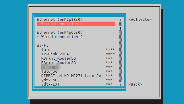
- Select the WiFi hotspot you want to connect to and enter the password. After a successful WIFI connection, a "*" will appear before the name of the connected WIFI.
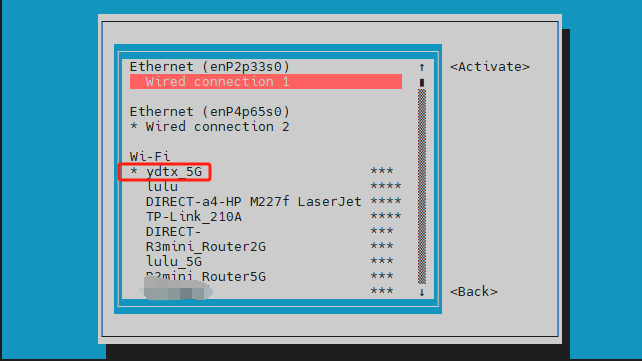
- You can view the WiFi IP address using the ip addr show wlan0 command
root@localhost:~# ip addr show wlan0
4: wlan0: <BROADCAST,MULTICAST,UP,LOWER_UP> mtu 1500 qdisc mq state UP group default qlen 1000
    link/ether f0:bf:bc:f6:3a:8e brd ff:ff:ff:ff:ff:ff
    inet 192.168.1.239/24 brd 192.168.1.255 scope global dynamic noprefixroute wlan0
       valid_lft 43173sec preferred_lft 43173sec
    inet6 fd85:d322:c276:0:50f8:7f68:84ea:2d9d/64 scope global noprefixroute
       valid_lft forever preferred_lft forever
    inet6 fe80::ad1f:8848:5dda:9c06/64 scope link noprefixroute
       valid_lft forever preferred_lft forever
- The ping command can test the connectivity of the WiFi network, and you can interrupt the ping command by pressing the Ctrl+C shortcut
root@localhost:~# ping -I wlan0 www.baidu.com
PING www.wshifen.com (103.235.46.115) from 192.168.1.239 wlan0: 56(84) bytes of data.
64 bytes from 103.235.46.115 (103.235.46.115): icmp_seq=1 ttl=47 time=195 ms
64 bytes from 103.235.46.115 (103.235.46.115): icmp_seq=2 ttl=47 time=164 ms
64 bytes from 103.235.46.115 (103.235.46.115): icmp_seq=3 ttl=47 time=188 ms
^C
--- www.wshifen.com ping statistics ---
4 packets transmitted, 3 received, 25% packet loss, time 3004ms
rtt min/avg/max/mdev = 164.471/182.364/194.691/12.950 ms
Testing methods for desktop image images
- Click the network configuration icon [Select Network] at the top right of the desktop. When testing WIFI, please do not connect to a network cable.
- After connecting to WiFi, you can open a browser to check if you can access the internet
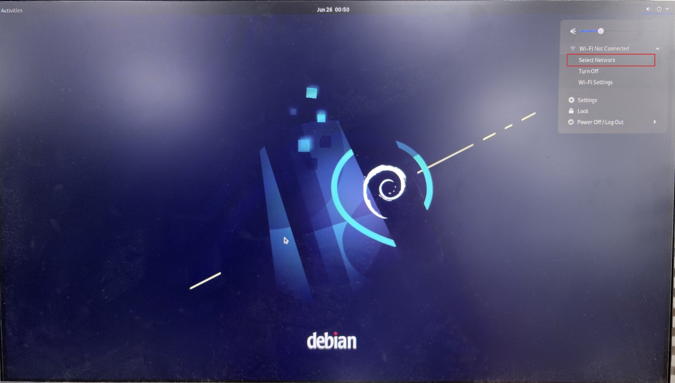
Network settings
3.4 BT
- Before using the Bluetooth feature, let's first check if the Bluetooth device node exists to make sure Bluetooth initializes properly.
root@localhost:/# hciconfig -a
hci0:   Type: Primary  Bus: UART
        BD Address: 67:B8:13:D7:E7:A4  ACL MTU: 1021:9  SCO MTU: 255:4
        UP RUNNING
        RX bytes:895 acl:0 sco:0 events:68 errors:0
        TX bytes:4499 acl:0 sco:0 commands:68 errors:0
        Features: 0xbf 0x2e 0x4d 0xfe 0xd8 0x3f 0x7b 0x87
        Packet type: DM1 DM3 DM5 DH1 DH3 DH5 HV1 HV3
        Link policy: RSWITCH SNIFF
        Link mode: SLAVE ACCEPT
        Name: 'localhost'
        Class: 0x3c0000
        Service Classes: Rendering, Capturing, Object Transfer, Audio
        Device Class: Miscellaneous,
        HCI Version:  (0xd)  Revision: 0xb
        LMP Version:  (0xd)  Subversion: 0xb
        Manufacturer: not assigned (2875)
- Next, you can use bluetoothctl to connect Bluetooth.
root@localhost:/# bluetoothctl
Agent registered
1. Enable Bluetooth controller
[bluetooth]# power on
Changing power on succeeded
2. Set the controller to be discoverable
[bluetooth]# discoverable on
Changing discoverable on succeeded
[CHG] Controller 67:B8:13:D7:E7:A4 Discoverable: yes
3. Set the controller to pairable
[bluetooth]# pairable on
Changing pairable on succeeded
4. Turn on Bluetooth device scanning
[bluetooth]# scan on
Discovery started
[CHG] Controller 67:B8:13:D7:E7:A4 Discovering: yes
[NEW] Device 46:A8:19:66:89:E0 xxxx
[NEW] Device 7D:E3:17:23:A6:6E xxxx
[NEW] Device 24:2A:EA:61:0F:28 Donleon  #Jot down the MAC address of the device you want to connect
5. Turn off scanning
[bluetooth]# scan off
Discovery stopped
[CHG] Device 24:2A:EA:61:0F:28 RSSI is nil
[CHG] Controller 67:B8:13:D7:E7:A4 Discovering: no
6. Set this device as a trusted device
[bluetooth]# trust 24:2A:EA:61:0F:28
[CHG] Device 24:2A:EA:61:0F:28 Trusted: yes
Changing 24:2A:EA:61:0F:28 trust succeeded
7. Pair with the device via MAC address
[bluetooth]# pair 24:2A:EA:61:0F:28
Attempting to pair with 24:2A:EA:61:0F:28
[CHG] Device 24:2A:EA:61:0F:28 Connected: yes
Request confirmation
[agent] Confirm passkey 227858 (yes/no): yes     #Enter 'yes' here, and you also need to confirm the pairing on your phone
[CHG] Device 24:2A:EA:61:0F:28 ServicesResolved: yes
[CHG] Device 24:2A:EA:61:0F:28 Paired: yes
Pairing successful    #When it shows that the pairing is successful here, we can exit (might need to wait a bit)
8. Exit
[Donleon]# exit
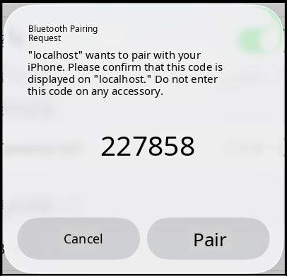
- If the Bluetooth device we need to connect is a phone, you'll need to download and enable the audio service. (If the Bluetooth device you want to connect is a headset/Bluetooth speaker, you don’t need to do the following steps.)
root@localhost:/# apt update
root@localhost:/# apt -y install pulseaudio-module-bluetooth
root@localhost:/# pulseaudio --start --system=false --realtime=false --log-target=journal
- Next, we can start the Bluetooth connection.
root@localhost:~# bluetoothctl #Re-enter bluetoothctl
Agent registered
1. View connected devices
[bluetooth]# paired-devices
Device 24:2A:EA:61:0F:28 Donleon
2. Connect Bluetooth device
[bluetooth]# connect 24:2A:EA:61:0F:28
Attempting to connect to 24:2A:EA:61:0F:28
[CHG] Device 24:2A:EA:61:0F:28 Connected: yes
Connection successful
[CHG] Device 24:2A:EA:61:0F:28 ServicesResolved: yes  #Just show that the connection is successful here
3. Remove Bluetooth device
[bluetooth]# remove 24:2A:EA:61:0F:28
[DEL] Device 24:2A:EA:61:0F:28 Donleon
Device has been removed
If you encounter the following error when connecting, try actively connecting to a device named 'localhost' on your phone:
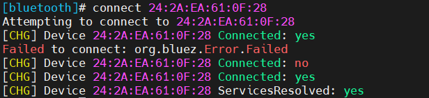
After a successful connection, it shows connected on the phone:

3.5 HDMI
| Model | Sige7 | Sige6 | Sige5 | Sige3 | Sige1 |
|---|---|---|---|---|---|
| Resolution | 8Kp60 | 4Kp60 | 4Kp120 | 4Kp60 | 4Kp60 |
- Connect the ArmSoM-Sige and HDMI monitor using an HDMI cable
- After starting the Linux system, if the HDMI monitor outputs images, it means the HDMI port is working properly
Note that although many laptops have HDMI ports, their HDMI ports generally only provide output functions and do not have HDMI in functionality, meaning they cannot display other devices' HDMI outputs on the laptop's screen. When you want to connect the HDMI port from the development board to the laptop's HDMI port, please first confirm that your laptop supports HDMI IN functionality. If HDMI does not display, please first check whether the system you are using is the desktop version; if it is the server version, only the terminal is visible
HDMI to VGA display test
- You need to prepare the following accessories
- HDMI to VGA converter
- A VGA cable supporting a VGA interface monitor
- The HDMI to VGA display test is as follows
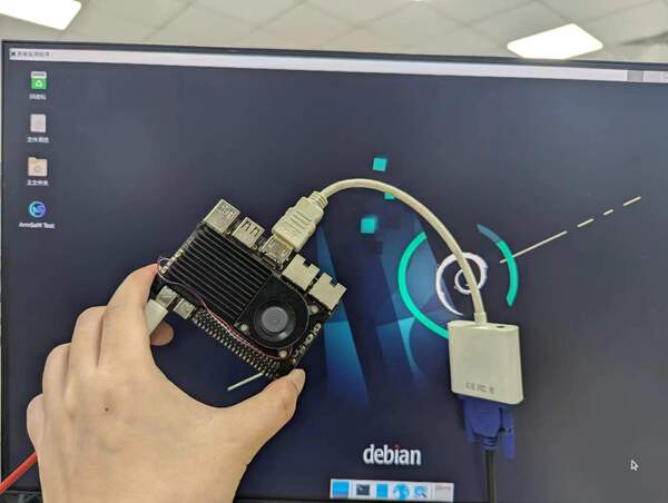
When using HDMI to VGA display, ArmSoM-Sige products and Linux systems require no configuration; the development board's HDMI port can display normally. So if the test shows problems, check the HDMI to VGA converter, VGA cable, and monitor for any issues.
3.6 USB
| Model | Sige6 |
|---|---|
| USB | 1* Type-C 3.0, 1x USB3.0, 3x USB2.0 |
USB ports allow you to connect a USB hub to expand the number of USB ports.
Connect a USB mouse or keyboard for testing
- Insert the keyboard with a USB interface into the USB port of the ArmSoM-Sige product
- Connect ArmSoM-Sige products to HDMI monitors
- If the mouse or keyboard works properly, the operating system means the USB port is working properly (the mouse can only be used on desktop systems).
Note: When connecting a mouse or keyboard, only USB 2.0 ports are allowed; USB 3.0 ports are not allowed
Testing by connecting USB storage devices
- First, insert a USB drive or USB external hard drive into the USB port of the ArmSoM-Sige product
- If you see the output of sdX by executing the following command, it means the USB drive has been successfully recognized
root@localhost:~# cat /proc/partitions | grep "sd*"
major minor  #blocks  name
   8        0   30720000 sda
   8        1   30718976 sda1
- You can use the mount command to mount the USB drive into /mnt, and then you can view the files on the USB drive
root@localhost:~# mount /dev/sda1 /test/
mount: /test: /dev/sda1 already mounted on /test.
- After mounting, you can use the df -h command to check the USB drive's capacity usage and mounting points
root@localhost:/test# df -h | grep "sd"
/dev/sda1        30G   64K   30G   1% /mnt
3.7 M.2 Key M
ArmSoM-Sige6 provides an M.2 Key M connector:
- The back of the product features an M.2 Key M connector. The board has a standard M.2 2280 mounting hole, allowing deployment of M.2 2280 NVMe SSDs.
Note: This M.2 interface does not support M.2 SATA SSDs.
You can use lsblk to check our hard drive devices. In the information listed below, nvme0n1 is our NVMe disk.
root@localhost:~# lsblk
NAME        MAJ:MIN RM  SIZE RO TYPE MOUNTPOINT
mtdblock0    31:0    0   16M  0 disk
mmcblk1     179:0    0 29.1G  0 disk
├─mmcblk1p1 179:1    0   32M  0 part
├─mmcblk1p2 179:2    0   16M  0 part
├─mmcblk1p3 179:3    0   96M  0 part
├─mmcblk1p4 179:4    0  7.3G  0 part /
├─mmcblk1p5 179:5    0   16M  0 part
└─mmcblk1p6 179:6    0 21.7G  0 part
nvme0n1     259:0    0 13.4G  0 disk
We can try to mount the NVMe disk to some empty directory.
root@localhost:~# mkdir temp
root@localhost:~# mount /dev/nvme0n1 temp
If the mount doesn't work, it might be because your NVMe drive is completely blank (no partition table) and doesn't have any file system. You can run the following command to format the drive to an ext4 file system and then try mounting it again.
root@localhost:~# mkfs.ext4 /dev/nvme0n1
3.8 Audio
Check the sound card in the system.
root@localhost:~# aplay -l
**** List of PLAYBACK Hardware Devices ****
card 0: allwinnerac101b [allwinner-ac101b], device 0: sunxi-snd-plat-i2s-ac101b-codec sunxi-ac101b.7-003e-0 []
  Subdevices: 1/1
  Subdevice #0: subdevice #0
card 1: allwinnerhdmi [allwinner-hdmi], device 0: sunxi-snd-plat-i2s-sunxi-snd-codec-hdmi soc@3000000:hdmi_codec- []
  Subdevices: 1/1
  Subdevice #0: subdevice #0
By default, onboard microphone recording is enabled, headphone microphones are turned off, and both onboard speakers and earpiece are turned on.
Record using the onboard microphone and execute the following command
root@localhost:~# arecord -D hw:0,0 -f S16_LE -r 44100 -c 2 -d 10 /tmp/test_mic1.wav
If recording with a headphone microphone, first turn off the onboard microphone, then turn on the headphone microphone and follow the command
root@localhost:~# amixer -c 0 cset name='MIC1 Switch' off  //The onboard microphone is mic1
root@localhost:~# amixer -c 0 cset name='MIC4 Switch' on  //The headset microphone is mic4
After turning on the headset microphone, you can perform the following command for testing (same as the recording command above).
root@localhost:~# arecord -D hw:0,0 -f S16_LE -r 44100 -c 2 -d 10 /tmp/test_mic2.wav
Play audio files
root@localhost:~# aplay -D hw:0,0 /tmp/test_mic1.wav (Playing the audio recorded with the headphones is replaced with test_mic2.wav)
3.9 FAN
Sige products are equipped with a 5V fan and use a 0.8mm connector
Use the echo command to set the fan speed: PWM control range is generally 0~255 (0 = stop, 255 = full speed).
- Since the system has temperature control, when we turn on the fan, if it reaches a certain temperature, it will automatically stop running. Therefore, during the following test, we can turn off the temperature control first and execute the following command
root@localhost:~# cat /sys/class/thermal/thermal_zone0/mode
enabled
root@localhost:~# cat /sys/class/thermal/thermal_zone1/mode
enabled
root@localhost:~# echo disabled > /sys/class/thermal/thermal_zone0/mode
root@localhost:~# echo disabled > /sys/class/thermal/thermal_zone1/mode
- After turning it off, you can follow these steps to adjust the fan speed
// Check current speed
root@localhost:~# cat /sys/class/hwmon/hwmon0/pwm1

//Set the fan to full speed
root@localhost:~# echo 255 > /sys/class/hwmon/hwmon0/pwm1

//Turn off the fan
root@localhost:~# echo 0 > /sys/class/hwmon/hwmon0/pwm1
3.10 40 PIN
Sige6 offers a 40-pin GPIO socket compatible with most sensor applications on the market.
wiring-armbian method
Download the wiringOP code to the development board wiring-armbian
- After downloading the wiringOP code, first compile and install it, then execute the following command:
root@localhost:/# cd wiring-armbian/
root@localhost:/wiring-armbian# ./build clean
root@localhost:/wiring-armbian# ./build
- After compilation, the output of the test gpio readall command is as follows
 root@localhost:/wiring-armbian# gpio readall
 +------+-----+--------+--------+---+   ARMSOM-SIGE6   +---+--------+--------+-----+------+
 | GPIO | wPi |   Name   |  Mode  | V | Physical | V |  Mode  | Name     | wPi | GPIO |
 +------+-----+----------+--------+---+----++----+---+--------+----------+-----+------+
 |      |     |     3.3V |        |   |  1 || 2  |   |        | 5V       |     |      |
 |  313 |   0 |    SDA.4 |    OFF | 0 |  3 || 4  |   |        | 5V       |     |      |
 |  312 |   1 |    SCL.4 |    OFF | 0 |  5 || 6  |   |        | GND      |     |      |
 |  356 |   2 |   PWM0-2 |    OFF | 0 |  7 || 8  | 0 | OFF    | TXD.1    | 3   | 354  |
 |      |     |      GND |        |   |  9 || 10 | 0 | OFF    | RXD.1    | 4   | 355  |
 |  357 |   5 |   PWM0-3 |    OFF | 0 | 11 || 12 | 0 | OFF    | PK0      | 6   | 320  |
 |  358 |   7 |   PWM0-4 |    OFF | 0 | 13 || 14 |   |        | GND      |     |      |
 |  359 |   8 |   PWM0-5 |    OFF | 0 | 15 || 16 | 0 | ALT7   | TXD.2    | 9   | 32   |
 |      |     |     3.3V |        |   | 17 || 18 | 0 | ALT7   | TXD.2    | 10  | 33   |
 |  108 |  11 |   MOSI.1 |    OFF | 0 | 19 || 20 |   |        | GND      |     |      |
 |  109 |  12 |   MISO.1 |    OFF | 0 | 21 || 22 | 0 | OFF    | PK6      | 13  | 326  |
 |  107 |  14 |   SCLK.1 |    OFF | 0 | 23 || 24 | 0 | OFF    | PD10     | 15  | 106  |
 |      |     |      GND |        |   | 25 || 26 | 0 | OFF    | PD15     | 16  | 111  |
 |  315 |  17 |    SDA.5 |    OFF | 0 | 27 || 28 | 0 | OFF    | SCL.5    | 18  | 314  |
 |  362 |  19 |   PWM0-8 |    OFF | 0 | 29 || 30 |   |        | GND      |     |      |
 |  321 |  20 |      PK1 |    OFF | 0 | 31 || 32 | 0 | OFF    | PWM0-7   | 21  | 361  |
 |  360 |  22 |   PWM0-6 |    OFF | 0 | 33 || 34 |   |        | GND      |     |      |
 |  322 |  23 |      PK2 |    OFF | 0 | 35 || 36 | 0 | OFF    | PD14     | 24  | 110  |
 |  325 |  25 |      PK5 |    OFF | 0 | 37 || 38 | 0 | OFF    | PK4      | 26  | 324  |
 |      |     |      GND |        |   | 39 || 40 | 0 | OFF    | Pk3      | 27  | 323  |
 +------+-----+----------+--------+---+----++----+---+--------+----------+-----+------+
 | GPIO | wPi |   Name   |  Mode  | V | Physical | V |  Mode  | Name     | wPi | GPIO |
 +------+-----+--------+--------+---+  ARMSOM-SIGE6  +---+-------+---------+-----+------+
- Set the GPIO port as output mode, where the third parameter requires the WPI index corresponding to the pin input
root@localhost:/wiring-armbian# gpio mode 1 out
- Set the GPIO port output to a high level. After setting, you can use a multimeter to measure the voltage at the pins. If it is 3.3V, it means the high level setting was successful
root@localhost:/wiring-armbian# gpio write 1 1
- Set the GPIO port output to low. After setting, you can use a multimeter to measure the voltage on the pins. If it is 0V, it means the low level was set successfully
root@localhost:/wiring-armbian# gpio write 1 0
- You can also read the current level status of the corresponding pin
root@localhost:/wiring-armbian# gpio read 1
0
- The other pin settings are similar; just change the wPi serial number to match the pin's serial number
3.11 RGB LED
The Sige6 features a user light (red light) and a power indicator (green light).
User red light By default, it is a heartbeat lamp, which can be controlled by the user.
The power indicator is green By default, its always-on mode means the system is running normally.
Users can control it via command
root@localhost:~# echo 0 > /sys/class/leds/armsom:red:user/brightness (Close)
root@localhost:~# echo 1 > /sys/class/leds/armsom:red:user/brightness (Light up)
root@localhost:~# echo heartbeat > /sys/class/leds/armsom:red:user/trigger (heartbeat light)
3.12 RTC
- Sige is equipped with an RTC IC LK8563S.
- First, use a 2-pin header to insert an RTC battery to power the RTC IC.
- Note that we should keep the RTC battery in the RTC connector and confirm that the RTC LK8563S device has been created
root@localhost:~# dmesg | grep rtc
[    3.247864] axp8191-rtcldo: supplied by regulator-dummy
[    9.306125] [drm] sunxi_de_bind crtc init for de 0 ok
[    9.306154] [drm] sunxi_de_bind crtc init for de 1 ok
[    9.972865] [drm] [SUNXI-CRTC]sunxi_crtc_atomic_enable
[   15.562369] rtc-hym8563 14-0051: no valid clock/calendar values available
[   15.592873] rtc-hym8563 14-0051: registered as rtc0
[   15.623103] rtc-hym8563 14-0051: no valid clock/calendar values available
[   15.642351] rtc-hym8563 14-0051: hctosys: unable to read the hardware clock
[   27.269249] [drm] [SUNXI-CRTC]sunxi_crtc_atomic_disable
[   27.298550] [drm] [SUNXI-CRTC]sunxi_crtc_atomic_enable
[   27.778616] [drm] [SUNXI-CRTC]sunxi_crtc_atomic_enable
[   28.317457] [drm] [SUNXI-CRTC]sunxi_crtc_atomic_disable
[  266.074667] rtc-hym8563 14-0051: no valid clock/calendar values available
[  347.201648] [drm] [SUNXI-CRTC]sunxi_crtc_atomic_disable
- Find rtc0, then use the following command to set the system time and sync to rtc0.
//Read the current time from the RTC chip; the first time you read it, there’s no clock
root@localhost:~# hwclock -r -f /dev/rtc0
[  164.582991][ T2179] rtc-hym8563 14-0051: no valid clock/calendar values available
hwclock: ioctl(RTC_RD_TIME) to /dev/rtc0 to read the time failed: Invalid argument

//Check the system's current time
root@localhost:~# date
Thu Jun 26 01:00:52 UTC 2025

//Set system time
root@localhost:~# date -s "2026-06-16 10:30:00"
Tue Jun 16 10:30:00 UTC 2026

//Write the system's current time to the RTC
root@localhost:~# hwclock -w -f /dev/rtc0

//Then read the current time from the RTC chip
root@localhost:~# hwclock -r -f /dev/rtc0
2026-06-16 10:31:02.465724+00:00
- Turn off the RTC battery, wait for 10 minutes or longer, then insert the RTC battery and start Sige6 to check the RTC time.
//Because the RTC lost power and its data, using the hwclock command can't read the clock.
root@localhost:~# hwclock -r -f /dev/rtc0
[  164.582991][ T2179] rtc-hym8563 14-0051: no valid clock/calendar values available
hwclock: ioctl(RTC_RD_TIME) to /dev/rtc0 to read the time failed: Invalid argument

//After resyncing the RTC with the system time, check the RTC clock again.
root@localhost:~# date  //Check the current system clock
Thu Jun 26 00:52:28 UTC 2025
root@localhost:~# hwclock -w -f /dev/rtc0  //Write
root@localhost:~# hwclock -r -f /dev/rtc0  //Read the RTC clock
2025-06-26 00:52:45.272526+00:00
3.13 MIPI-CSI
The MIPI-CSI interface supports 0v13850 camera-module1 and imx219 cameras
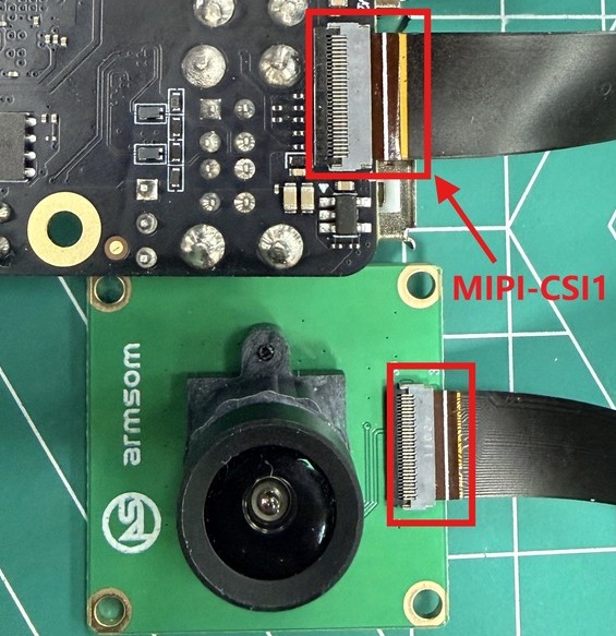
- Connect the camera-module1 to the MIPI-CSI1 interface on the back of the development board, as shown in the picture:
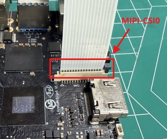
- Connect the IMX219 camera to the MIPI-CSI0 interface on the front of the development board, as shown in the picture:
3.13.1 Using the ArmSoM camera-module1
You can download test files csi_test_mplane Cloud drive path:ArmSoM-Sige6 → software → Camera testing program and push it to the development board for execution.
root@localhost:/# chmod +x csi_test_mplane
root@localhost:/# ./csi_test_mplane 8 0 2112 1568 ./ 5 5
open /dev/video8 fd = 3
resolution got from sensor = 2112*1568 num_planes = 1
VIDIOC_STREAMON ok
file length = 6623232 0 0
file start = 0x7fb7f1f000 (nil) (nil)
file length = 6623232 0 0
file start = 0x7fb78ce000 (nil) (nil)
file length = 6623232 0 0
file start = 0x7fb727d000 (nil) (nil)
file length = 6623232 0 0
file start = 0x7fb6c2c000 (nil) (nil)
VIDIOC_STREAMOFF ok
mode 5 test done at the 0 time!!
time cost 0.339447(s)
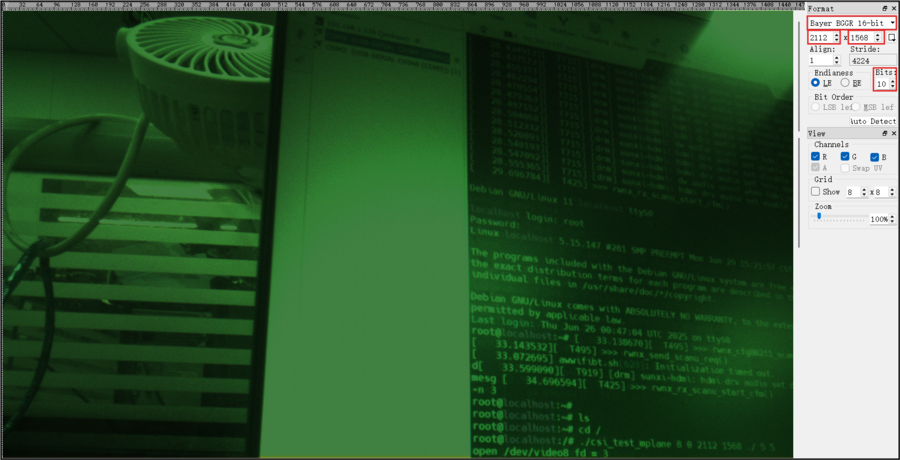
After executing the above command, you can see that some fb8y5_2112_1568*.bin files have been generated in the current directory. We can use the 7yuv software to view the RAW images and select the corresponding parameters as shown in the figure below:
3.13.2 Using the IMX219 camera
The testing method is the same as above, using the following command
root@localhost:/# ./csi_test_mplane 0 0 1920 1080 ./ 5 5
After completing the above tests, you can check the camera nodes
root@localhost:/# cat /sys/kernel/debug/mpp/vi
*****************************************************
VIN hardware feature list:
mcsi 3, ncsi 2, parser 3, isp 1, vipp 4, dma 6
CSI_VERSION: CSI300_500, ISP_VERSION: ISP602_100
CSI_CLK: 324000000, ISP_CLK: 324000000
*****************************************************
vi0:
imx219 => mipi2 => csi2 => isp0 => vipp0
input => hoff: 0, voff: 0, w: 1920, h: 1080, fmt: RGGB10
output => width: 1920, height: 1080, fmt: RAW10
interface: MIPI, isp_mode: NORMAL, hflip: 0, vflip: 0
prs_in => x: 1920, y: 1080, hb: 2738, hs: 3407
bkuf => cnt: 5 size: 4177920 rest: 5, work_mode: online
frame => cnt: 21, lost_cnt: 0, error_cnt: 0
internal => avg: 33(ms), max: 33(ms), min: 33(ms)
CSI Bandwidth: 0
*****************************************************
vi8:
ov13850_mipi => mipi1 => csi1 => isp0 => vipp8
input => hoff: 0, voff: 0, w: 2112, h: 1568, fmt: BGGR10
output => width: 2112, height: 1568, fmt: RAW10
interface: MIPI, isp_mode: NORMAL, hflip: 0, vflip: 0
prs_in => x: 2112, y: 1568, hb: 3811, hs: 2667
bkuf => cnt: 5 size: 6623232 rest: 4, work_mode: online
frame => cnt: 6, lost_cnt: 0, error_cnt: 0
internal => avg: 33(ms), max: 33(ms), min: 33(ms)
CSI Bandwidth: 0
*****************************************************
3.14 MIPI DSI
ArmSoM-Sige6 offers a maximum resolution of up to 4K@60Hz
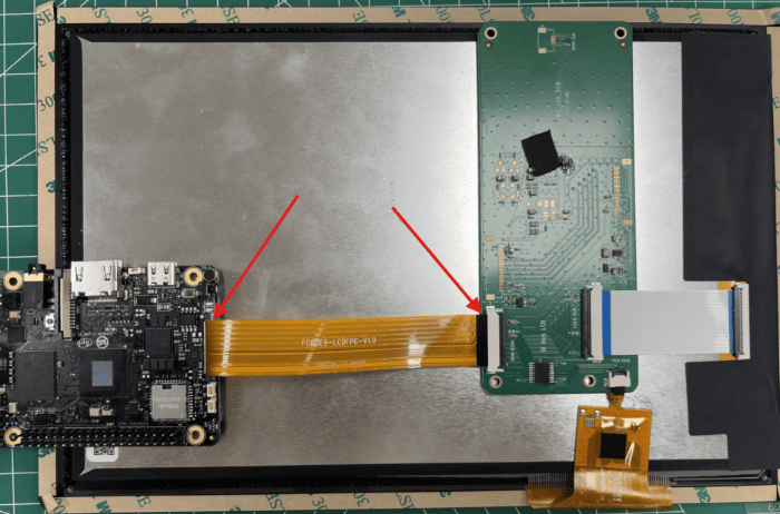
- Connect the ribbon cable as shown in the picture below
- By default, the system turns off the MIPI-DSI screen. To turn it on, you need to go to the SDK to open the corresponding node in the device tree
3.15 CPU/GPU/NPU/DDR
Below are the methods for setting CPU, GPU, NPU, DDR, frequency fixing, and performance mode settings for the ArmSoM-Sige6
Fixed frequency
Change CPU frequency
The ArmSoM-Sige6 CPUs consist of 6 A55 + 2 A76 CPUs, divided into 3 groups managed separately. The nodes are:
root@localhost:~# ls /sys/devices/system/cpu/cpufreq/policy0:(Corresponding to 6 A55: CPU0-5)
affected_cpus                  scaling_cur_freq
cpuinfo_cur_freq               scaling_driver
cpuinfo_max_freq               scaling_governor
cpuinfo_min_freq               scaling_max_freq
cpuinfo_transition_latency     scaling_min_freq
related_cpus                   scaling_setspeed
scaling_available_frequencies  stats
scaling_available_governors

root@localhost:~# ls /sys/devices/system/cpu/cpufreq/policy6:(Corresponding to 2 A76: CPU6-7)
affected_cpus                  scaling_cur_freq
cpuinfo_cur_freq               scaling_driver
cpuinfo_max_freq               scaling_governor
cpuinfo_min_freq               scaling_max_freq
cpuinfo_transition_latency     scaling_min_freq
related_cpus                   scaling_setspeed
scaling_available_frequencies  stats
scaling_available_governors


root@localhost:~# cat /sys/devices/system/cpu/cpufreq/policy6/scaling_available_frequencies //Get the current CPU-supported frequency points
416000 780000 1014000 1196000 1404000 1508000 1612000 1716000 1794000 1898000 1950000 2002000
root@localhost:~# cat /sys/devices/system/cpu/cpufreq/policy6/scaling_available_governors // Get the CPU running mode
conservative ondemand userspace powersave performance schedutil
The default is automatic frequency mode: schedutil (if you want to restore it, just set it to this mode)
Set manual frequency
# cat /sys/devices/system/cpu/cpufreq/policy6/cpuinfo_cur_freq
416000   //Check current frequency
# echo userspace > /sys/devices/system/cpu/cpufreq/policy6/scaling_governor  //Manual fixed-frequency mode: userspace
# echo 1612000 > /sys/devices/system/cpu/cpufreq/policy6/scaling_setspeed  Set the frequency to 1612000
# cat /sys/devices/system/cpu/cpufreq/policy6/cpuinfo_cur_freq  // Check if it's set up successfully
1612000
#
The other two sets of CPUs are set up in a similar way, just operate the corresponding nodes.
Change GPU frequency
GPU node path
root@localhost:~# ls /sys/class/devfreq/1800000.gpu
available_frequencies  max_freq               subsystem
available_governors    min_freq               target_freq
cur_freq               name                   timer
device                 polling_interval       trans_stat
governor               power                  uevent
root@localhost:~# cat /sys/class/devfreq/1800000.gpu/available_frequencies // Get GPU-supported frequency bands
400000000 600000000 800000000 1008000000
root@localhost:~# cat /sys/class/devfreq/1800000.gpu/available_governors // Get the GPU running mode
sunxi_actmon userspace performance simple_ondemand
The default is the automatic frequency conversion mode: simple_ondemand (to restore it, just set it to this mode).
Set manual frequency
root@localhost:~# cat /sys/class/devfreq/1800000.gpu/cur_freq //Check current frequency
400000000
root@localhost:~# echo userspace > /sys/class/devfreq/1800000.gpu/governor // Manual fixed-frequency mode: userspace
root@localhost:~# echo 600000000 > /sys/class/devfreq/1800000.gpu/userspace/set_freq // Set the frequency to 600,000,000
root@localhost:~# cat /sys/class/devfreq/1800000.gpu/cur_freq  // Check if it's set up successfully
600000000
Note: When setting the GPU frequency, you need to keep clicking or sliding the touchscreen (to refresh the GPU)
Change DDR frequency
DDR node path
root@localhost:~# ls /sys/class/devfreq/a020000.dmcfreq/
available_frequencies  max_freq               target_freq
available_governors    min_freq               trans_stat
cur_freq               name                   uevent
device                 power
governor               subsystem
root@localhost:~# cat /sys/class/devfreq/a020000.dmcfreq/available_frequencies // Get DDR-supported frequency points
400000000 800000000 1200000000 2400000000
root@localhost:~# cat /sys/class/devfreq/a020000.dmcfreq/available_governors // Get the DDR operating mode
sunxi_actmon userspace performance simple_ondemand
The default is the automatic frequency mode: performance (if you want to restore it, just set it to this mode)
Set manual frequency
root@localhost:~# cat /sys/class/devfreq/a020000.dmcfreq/cur_freq // Check current frequency
2400000000
root@localhost:~# echo userspace > /sys/class/devfreq/a020000.dmcfreq/governor // Manual fixed-frequency mode: userspace
root@localhost:~# echo 1200000000 > /sys/class/devfreq/a020000.dmcfreq/userspace/set_freq  // Set the frequency to 1200000000
root@localhost:~# cat /sys/class/devfreq/a020000.dmcfreq/cur_freq   // Check if the setup was successful
1200000000
Change NPU frequency
NPU's node path
root@localhost:~# ls /sys/class/devfreq/3600000.npu/
available_frequencies  max_freq               target_freq
available_governors    min_freq               trans_stat
cur_freq               name                   uevent
device                 power
governor               subsystem
root@localhost:~# cat /sys/class/devfreq/3600000.npu/available_frequencies     // Get the frequency bands supported by the NPU
492000000 852000000 1008000000
root@localhost:~# cat /sys/class/devfreq/3600000.npu/available_governors // Get the mode in which the NPU is running
sunxi_actmon userspace performance simple_ondemand
The default is the automatic frequency mode: performance (if you want to restore it, just set it to this mode).
Set manual frequency
root@localhost:~# cat /sys/class/devfreq/3600000.npu/cur_freq //Check current NPU frequency
1008000000
root@localhost:~# echo userspace > /sys/class/devfreq/3600000.npu/governor // Manual fixed-frequency mode: userspace
root@localhost:~# mount -t debugfs none /sys/kernel/debug
root@localhost:~# echo 852000000 > /sys/kernel/debug/viplite/clk_freq // Set the frequency to 852000000
root@localhost:~# cat /sys/class/devfreq/3600000.npu/cur_freq  // Check if the setup was successful
852000000
root@localhost:~# cat /sys/kernel/debug/rknpu/load // Check the NPU load
NPU load:  Core0:  0%, Core1:  0%, Core2:  0%,
Performance Mode
root@localhost:~# echo performance > /sys/devices/system/cpu/cpufreq/policy0/scaling_governor
root@localhost:~# echo performance > /sys/class/devfreq/1800000.gpu/governor
root@localhost:~# echo performance > /sys/class/devfreq/a020000.dmcfreq/governor
root@localhost:~# echo performance > /sys/class/devfreq/3600000.npu/governor
Product Certificate
CE / FCC / RoHS
Supply Statement
The ArmSoM-Sige6 will be produced at least until January 2036.
Accessories
Purchase Samples
ArmSoM online shop: ArmSoM Aliexpress online shop:
ArmSoM Taobao shop: https://item.taobao.com/item.htm?id=1091107450553
OEM&ODM, please contact: sales@armsom.org
What do others say about the Sige6?
Notes
- Before handling the device, please ensure you wear an anti-static wrist strap or take electrostatic discharge measures to prevent damage to the development board.
- Assembly should be performed in an electrostatic-safe environment, avoiding operations in dry and low-humidity conditions.
- When not in use, store the device in an anti-static bag and keep it in a suitably temperature-controlled, low-humidity environment to prevent static electricity buildup.
- When handling the device, avoid friction or collisions to prevent the generation of static electricity that could cause damage.
- When holding the device, try to avoid direct contact with the chips on the mainboard to prevent static damage.
- Do not plug or unplug wires or other devices while the device is operating to avoid damage from electrical surges.
- When connecting or disconnecting the GPIO/MIPI expansion interfaces, make sure to turn off the power and disconnect the power cable to prevent damage from electrical current.
Without effective cooling measures, the surface temperature of the main chip may exceed 60 degrees. When handling the device, please avoid direct contact with the SoC and surrounding power inductors to prevent burns. Ensure that the environment is well-ventilated during operation to prevent localized heat buildup, which could lead to overheating. Additionally, do not place the device in direct sunlight.