Product Introduction: Sige7s
Let's get to know Sige7s in 5 minutes.
Overview
The ArmSoM-Sige7s is powered by Rockchip's latest flagship RK3588s,octa-core 64-bit processor, with a max frequency of 2.4GHz, a 6 TOPS NPU, and up to 32GB of RAM.
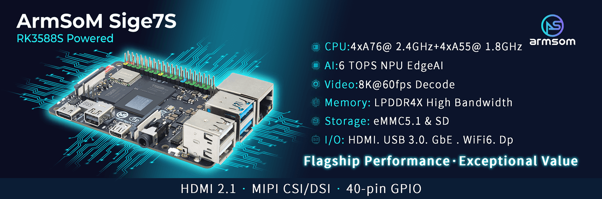
Sige7s is applied for various applications,such as, ARM PCs, edge computing, cloud servers, AI, cloud computing, virtual/augmented reality, blockchain, smart NVRs and more.
Key Parameter
- SoC: Rockchip RK3588s
- CPU: 4x Cortex-A76 @ 2.4GHz + 4x Cortex-A55 @ 1.8GHz, 8nm
- GPU: ARM Mali-G610 MP4
- NPU: Up to 6 TOPS (INT8), supports INT4/INT8/INT16 mixed computing
- VPU/Codec:
- Hardware Decode: 8K@60fps H.265/VP9/AVS2, 8K@30fps H.264 AVC/MVC, 4K@60fps AV1, 1080P@60fps MPEG-2/-1/VC-1/VP8
- Hardware Encode: 8K@30fps H.265 / H.264
- RAM: 2GB/4GB/8GB/16GB/32GB (max 32GB) 64bit LPDDR4/LPDDR4x
- Storage: 32GB/64GB/128GB eMMC Module
- WIFI/BT: IEEE 802.11a/b/g/n/ac/ax WIFI6 and BT5
- Operating Voltage: Wide input voltage, 5V to 23V (±5% tolerance)
- Operating temperature: 0°C ~ 80°C
- OS:
- Official: Debian 11, Ubuntu 22.04, Ubuntu 24.04
- 3rd party: Armbian, Arch Linux, openSUSE
- PCB: 12-layer
- Weight: 46.6g
- Size: 92mm × 62mm x 14.6mm
Getting started
Sige7s User Manual
How to get started with your Sige7s
Hardware
Hardware Interface
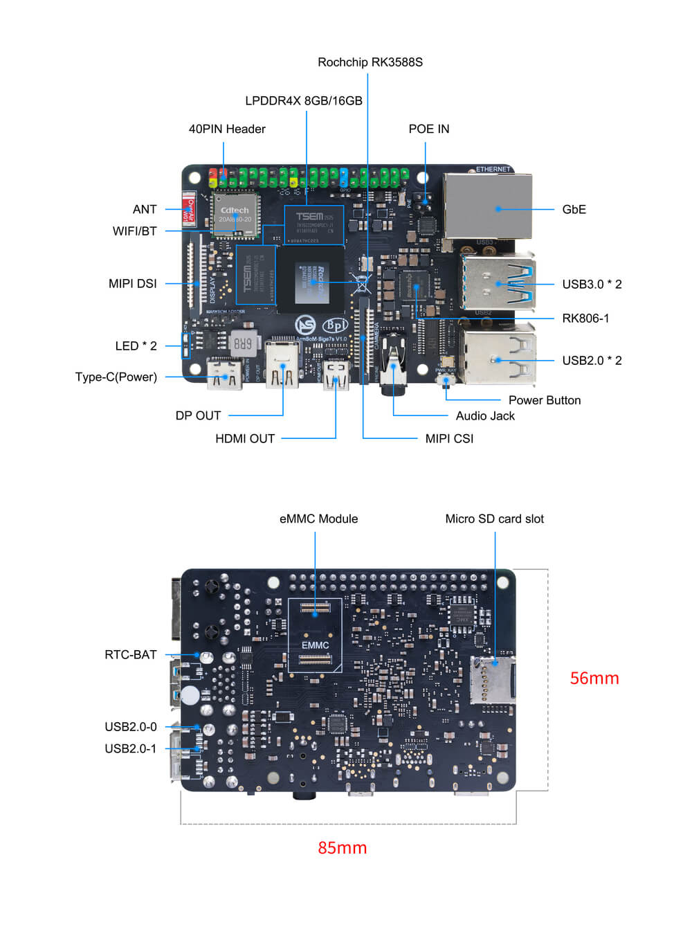
Hardware Spec
Sige7s Hardware Specifications
| Category | Functional Parameters |
|---|---|
| SOC | |
| CPU | |
| GPU | |
| NPU | |
| VPU / Codec | |
| ISP | |
| RAM | |
| Flash | |
| Networking | |
| Video Output | |
| Video Input | |
| Audio | |
| USB Interfaces | |
| 40-PIN | |
| Others | |
| Power Supply | |
| Buttons | |
| OS Support | |
| Dimensions | |
| Operating Temp |
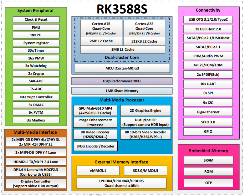
RK3588s Block Diagram
RK3588s Block Diagram
Hardware Pin Definitions
40-PIN header
| GPIO number | Function | Pin | Pin | Function | GPIO number |
|---|---|---|---|---|---|
| +3.3V | 1 | 2 | +5.0V | ||
| /dev/i2c1 sda | I2C1_SDA \ GPIO0_D5 | 3 | 4 | +5.0V | |
| /dev/i2c1 scl | I2C1_SCL \ GPIO0_D4 | 5 | 6 | GND | |
| 47 | GPIO1_B7 \ PWM3_M3 | 7 | 8 | UART2_TX_M0 | |
| GND | 9 | 10 | UART2_RX_M0 | ||
| 128 | GPIO4_A0 | 11 | 12 | GPIO1_A7 | 39 |
| 129 | GPIO4_A1 | 13 | 14 | GND | |
| 130 | GPIO4_A2 | 15 | 16 | UART6_TX_M1 \ GPIO1_A1 | /dev/ttyS2 uart txd |
| +3.3V | 17 | 18 | UART6_RX_M1 | GPIO1_A0 | /dev/ttyS2 uart rxd | |
| spi mosi | SPI0_MOSI_M2 | 19 | 20 | GND | |
| spi miso | SPI0_MISO_M2 | 21 | 22 | GPIO1_B0 | 40 |
| spi clk | SPI0_CLK_M2 | 23 | 24 | spi cs 0 | SPI0_CS0_M2 |
| GND | 25 | 26 | spi cs 1 | SPI0_CS1_M2 | |
| /dev/i2c6 sda | I2C6_SDA_M3 | 27 | 28 | I2C6_SCL_M3 | /dev/i2c6 scl |
| 131 | GPIO4_A3 \ UART0_TXD_M2 | 29 | 30 | GND | |
| 132 | GPIO4_A4 \ UART0_RXD_M2 | 31 | 32 | PWM2 | 105 |
| 133 | GPIO4_A5 \ UART3_TXD_M2 | 33 | 34 | GND | |
| 134 | GPIO4_A6 \ UART3_RXD_M2 | 35 | 36 | GPIO4_B2 \ CAN1_RXD_M1 | 138 |
| 135 | GPIO4_A7 | 37 | 38 | GPIO4_B3 \ CAN1_TXD_M1 | 139 |
| GND | 39 | 40 | GPIO3_C3 | 115 |
MIPI CSI
| PIN | Name |
|---|---|
| 1 | VCC_CAM(3.3v) |
| 2 | I2C8_SDA_M2 |
| 3 | I2C8_SCL_M2 |
| 4 | CIF_CLKOUT |
| 5 | PWDN_GPIO1_A6 |
| 6 | GND |
| 7 | MIPI_CSI_RX_CLK0P |
| 8 | MIPI_CSI_RX_CLK0N |
| 9 | GND |
| 10 | MIPI_CSI_RX_D1P |
| 11 | MIPI_CSI_RX_D1N |
| 12 | GND |
| 13 | MIPI_CSI_RX_D0P |
| 14 | MIPI_CSI_RX_D0N |
| 15 | GND |
MIPI DSI
0.5mm FPC connector (J11)
| PIN | Name |
|---|---|
| 1 | VCC_MIPI |
| 2 | VCC_MIPI |
| 3 | GND |
| 4 | I2C4_SDA_M3 |
| 5 | I2C4_SCL_M3 |
| 6 | GND |
| 7 | MIPI_DSI_TX1_D0P |
| 8 | MIPI_DSI_TX1_D0N |
| 9 | GND |
| 10 | MIPI_DSI_TX1_CLKP |
| 11 | MIPI_DSI_TX1_CLKN |
| 12 | GND |
| 13 | MIPI_DSI_TX1_D1P |
| 14 | MIPI_DSI_TX1_D1N |
| 15 | GND |
VRTC
0.8mm connector(J18)
| Pin | Assignment | Description |
|---|---|---|
| 1 | + | Positive pole |
| 2 | - | Negative pole |
Resources
Source Code
ArmSom-bsp
Building a Linux System
Armbian
Armbian Linux build framework
Sige7s kernel
Improved Rockchip Linux
Sige7s uboot
ArmSoM/u-boot
Sige7s mainline linux
torvalds linux
RKNN-LLM
AI models to Rockchip chips
Cloud drive link
Google Drive links in general, including software materials and hardware materials
Official mirror
ArmSoM team uses Debian bullseye as the official operating system.How to Flash Image📤
Download
The following systems have been tested and verified by ArmSoM official:
| logo | Description | Cloud drive path |
|---|---|---|
 | debian12 for Sige7s : Debian 12 brings thousands of new and updated packages, supporting multiple desktop environments and processor architectures (including 32-bit and 64-bit PC, ARM, MIPS, and PowerPC). But one of the biggest changes is the upgrade of the Linux kernel from version 5.10 to version 6.1 LTS. | ArmSoM->ArmSoM-Sige7s->software->Debianfirmware |
 | ubuntu22.04 for Sige7s : Ubuntu 22.04, code-named 'Jammy Jellyfish', is a version officially released by Canonical on April 21, 2022. | ArmSoM->ArmSoM-Sige7s->software->Ubuntufirmware |
Third Party System
| logo | Description | Download |
|---|---|---|
 | Armbian for Sige7s: Armbian is a computing build framework that lets users create ready-to-use images with a working kernel based on the variable user space configurations of various single-board computers. It provides a variety of pre-built images for some supported single-board computers, usually based on Debian or Ubuntu. | armbian firmware download |
Hardware Resources
Get the Sige7s schematics, DXF, and other hardware files. Cloud drive path: ArmSoM-Sige7s → hardware Files
V1.1
- VOL_IC: U27/U7/U6301change part pin;
- USB:U15 fr o m TypeC1 change t o TypeC0; CN31 fr o m USB3. 0 change t o USB2. 0;
- 40PIN:add UART Pr ot ect; J 2&CN2&CN32 change t o WF0. 8;
- CAM:DEL R6352, CSI _1 I2C3 change t o I2C4;
- WIFI Module: AP6275S change to AP6275P;
User manual
1. Preparation for getting started
Before you start using the ArmSoM-Sige7s product, please get the following items ready
Tools ready
- Power supply
- System Installation (Choose One)
- Onboard eMMC startup
- The USB Type-C cable provides power, and the USB dual-male cable is used for flashing. To write the image from a USB 3.0 port to the Sige7s, you need to use the USB dual-male cable to connect the Sige series to the PC, while using the USB Type-C cable to power the Sige7s through its Type-C port.
- MicroSD card/TF card boots
- MicroSD card/TF card, Class 10 or above, at least 8GB SDHC, and card reader
- Here are the high-speed TF cards tested and verified by the ArmSoM team
- SanDisk 32GB TF (MicroSD) Dashcam & Security Monitoring Dedicated Storage Card (Recommended for Long-Term Operation)
- SanDisk 32GB TF (MicroSD) Storage Card for Dashcams & Security Monitoring (Recommended for Long-Term Use)
- SanDisk TF 8GB Class10 microSD
- SanDisk TF 128G Class10 microSD XC TF 128G 48MB/S:
- Onboard eMMC startup
You can set Sige as a desktop interactive computer, or you can set it as a headless computer that can only be accessed through the network. To set Sige as a headless computer, you configure the hostname, user accounts, network connections, and SSH during the initial installation of the operating system. If you want to use Sige directly, you will need the following additional accessories:
Optional options
- Keyboard & Mouse
- HDMI monitor, DP monitor, HDMI cable, and DP cable
- Ethernet cable (network cable)
- Camera module
- It is recommended to use imx219 module.
- LCD display
- It's recommended to use the Waveshare 7-inch 800×480 LCD screen.
- 3.5mm wired headphones with a microphone.
Power supply
The table below shows the power specifications required to power the ArmSoM-Sige7s. You can use any high-quality power supply that provides the correct power mode.
| Model | Recommended Power Supply (Voltage/Current) | Power supply mode |
|---|---|---|
| Sige7s | 5V/3A | USB Type-C |
Plug the power into the port labeled "PWR IN", and make sure to use the correct port!
Account needed to log in
| Username | Password |
|---|---|
| root | root |
| armsom | armsom |
2. Choose Burning Method
ArmSoM-sige7s supports booting from eMMC or SD card. Below, we'll introduce two ways to flash the firmware onto eMMC or SD card, and how to erase the SPI Flash.
2.1 Flash the firmware to the eMMC
- To put the ArmSoM-sige7s into flashing mode, you need to short the pins as shown in the picture below. To enter Maskrom mode, short the Maskrom pin to the GND pin, and to enter Loader mode, short the Recovery pin to the GND pin.
- The ArmSoM-sige7s is programmed using a USB dual male cable, with one end connected to the onboard USB 3.0 port and the other end to the computer, while also using a USB Type-C cable to power the development board.
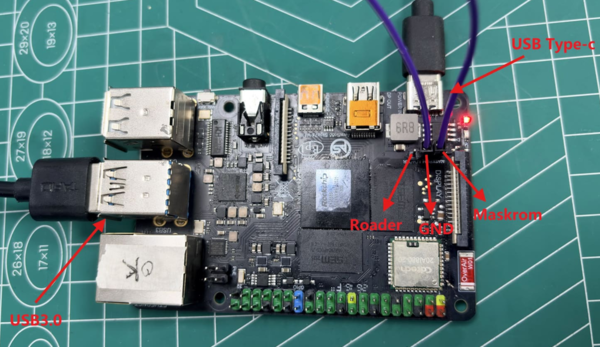
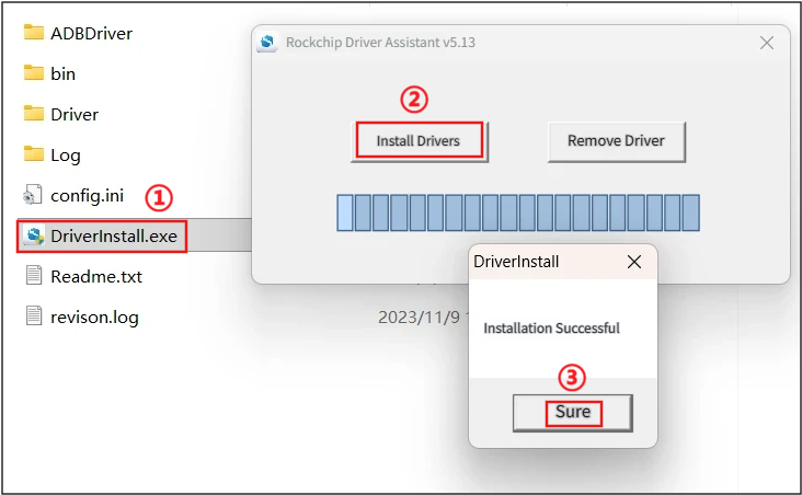
After connecting everything as described above, let's first install the USB driver. Open RK Driver Assistant and follow steps ①②③:
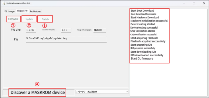
After installing the driver, open the flashing tool RKDevTool and check what mode is recognized at ④. If it shows Maskrom mode or Loader mode, you can click ① to select the firmware, then click ② to upgrade, and keep going until the info bar on the right shows that the firmware upgrade is complete.
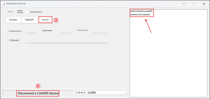
If the spot marked ④ above shows 'ADB device found' and you want to switch to flashing mode, click the switch at ③ in the picture until it shows 'Switch to Rockusb successful'. Wait for a moment, and you'll see ④ display as Maskrom mode or Loader mode. At this point, you can go back to step two to upgrade the firmware.
2.2 Flash the firmware to the SD card
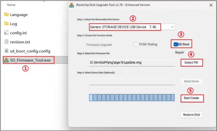
- Insert the SD card into the SD card reader, connect it to the computer, then double-click to run SD_Firmware_Tool.exe and follow steps ①②③:
2.3 Erase SPI Flash
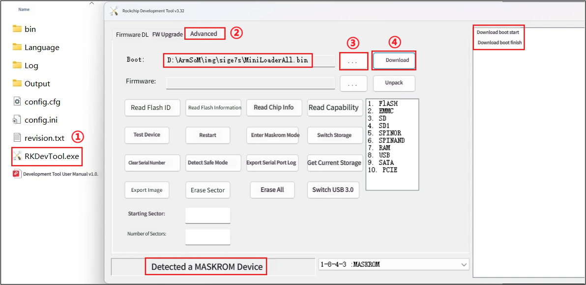
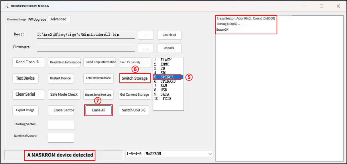
- Sometimes you might encounter firmware upgrade failures or anomalies, or leftover boot data in the eMMC or SPI Nor Flash interfering with the startup of the new system. In such cases, we can try erasing the Flash data first to force the device into Maskrom mode, and then reload the firmware. You can do it as follows:
- ① Open the burning tool RKDevTool, ② select Advanced Features, ③ choose the MiniLoaderAll.bin firmware, ④ click Download and wait for it to finish.
- ⑤ Select the storage device as SPINOR, ⑥ click switch storage, ⑦ click erase all, and wait until the erasure is complete
3. Interface usage
If this is your first time using the ArmSoM-Sige7s product, please get familiar with the product's hardware interfaces first so you can better understand the content that follows.
| Hardware interfaces | Sige7s |
|---|
3.1 Debugging the serial port
Connect the USB-to-TTL serial cable to the 40-pin socket on the board as shown:
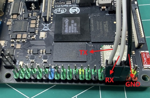
| Sige7s | Connection | Serial port module |
|---|---|---|
| GND(Pin6) | ---> | GND |
| TX(Pin8) | ---> | RX |
| RX(Pin10) | ---> | TX |
Serial communication parameters
- Port rate: 1500000
- Data bits: 8
- Stop position: 1
- Checksum bits: None
- Flow control: None
3.2 Ethernet Port
- First, plug one end of the Ethernet cable into the ArmSoM-Sige7s Ethernet port, and connect the other end to the router, making sure the network is working properly.
- After the system starts, it will automatically assign an IP address to the Ethernet card via DHCP, no other configuration is needed.
- The command to check the IP address on the Linux system of ArmSoM-Sige7s is shown below, where enP4p65s0 is the name of the Ethernet card device.
armsom@armsom:~$ ip a
1: lo: <LOOPBACK,UP,LOWER_UP> mtu 65536 qdisc noqueue state UNKNOWN group default qlen 1000
    link/loopback 00:00:00:00:00:00 brd 00:00:00:00:00:00
    inet 127.0.0.1/8 scope host lo
       valid_lft forever preferred_lft forever
    inet6 ::1/128 scope host noprefixroute
       valid_lft forever preferred_lft forever
2: dummy0: <BROADCAST,NOARP> mtu 1500 qdisc noop state DOWN group default qlen 1000
    link/ether e2:98:22:4b:3e:f1 brd ff:ff:ff:ff:ff:ff
3: enP4p65s0: <BROADCAST,MULTICAST,UP,LOWER_UP> mtu 1500 qdisc mq state UP group default qlen 1000
    link/ether 00:55:7b:b5:7d:f7 brd ff:ff:ff:ff:ff:ff
    inet 192.168.1.132/24 brd 192.168.1.255 scope global dynamic noprefixroute enP4p65s0
       valid_lft 43178sec preferred_lft 43178sec
    inet6 fd45:d3b4:e549::467/128 scope global dynamic noprefixroute
       valid_lft 43176sec preferred_lft 43176sec
    inet6 fd45:d3b4:e549:0:3ea4:eaca:17e4:ad67/64 scope global dynamic noprefixroute
       valid_lft 5377sec preferred_lft 2677sec
    inet6 fe80::465b:fc4c:ca13:37e4/64 scope link noprefixroute
       valid_lft forever preferred_lft forever
4: wlan0: <NO-CARRIER,BROADCAST,MULTICAST,UP> mtu 1500 qdisc mq state DOWN group default qlen 1000
    link/ether 0c:cd:d0:e0:96:d3 brd ff:ff:ff:ff:ff:ff
There are three ways to check the IP address after starting ArmSoM-Sige7s:
- Connect an HDMI or DP monitor, then log into the system and use the terminal to type the 'ip a' command to check the IP address
- Connect to the debug serial port and enter the command 'ip a' in the terminal to check the IP address
- If you don't have a debug serial port or an HDMI monitor, you can still check the IP address of the ArmSoM-Sige7s network port through the router's management interface. However, many people often can't see the ArmSoM-Sige7s IP address this way. If you can't see it, the debugging method is as follows:
- First, check if the Linux system has started normally. If the green light on the ArmSoM-Sige7s is steady, it usually means it has started properly. If only the red light is on, it means the system hasn’t started correctly.
- Check if the network cable is plugged in properly, or try a different cable.
- Try another router. Router issues are pretty common, like the router not assigning an IP address properly, or even if it has assigned an IP address, you might not see it in the router.
- If you don’t have another router, you’ll have to connect an HDMI display or use the debug serial port to check the IP address.
Another thing to note is that ArmSoM-Sige7s automatically assigns IP addresses via DHCP, so no setup is needed.
- Use the ping tool to check if the network is connected.
The command to test network connectivity is as follows, and the ping command can be interrupted using the Ctrl+C shortcut.
armsom@armsom:~$ sudo ping -I enP4p65s0 www.baidu.com
PING www.wshifen.com (103.235.46.115) from 192.168.1.132 enP4p65s0: 56(84) bytes of data.
64 bytes from 103.235.46.115 (103.235.46.115): icmp_seq=1 ttl=47 time=156 ms
64 bytes from 103.235.46.115 (103.235.46.115): icmp_seq=2 ttl=47 time=157 ms
64 bytes from 103.235.46.115 (103.235.46.115): icmp_seq=7 ttl=47 time=156 ms
64 bytes from 103.235.46.115 (103.235.46.115): icmp_seq=11 ttl=47 time=156 ms
64 bytes from 103.235.46.115 (103.235.46.115): icmp_seq=12 ttl=47 time=158 ms
^C
--- www.wshifen.com ping statistics ---
12 packets transmitted, 5 received, 58.3333% packet loss, time 11087ms
rtt min/avg/max/mdev = 155.723/156.571/157.717/0.699 ms
Only regular users need to use sudo; the root user doesn't.
3.3 WIFI
ArmSoM-Sige7s is an onboard WiFi module and antenna, no need for an external network device or external antenna.
The server version image connects to Wi-Fi via command
- First, log in to the Linux system; there are three ways to do this:
- If the ArmSoM-Sige7s is connected to a network cable, you can use SSH to remotely log in to the Linux system.
- If the ArmSoM-Sige7s is connected to a debug serial port, you can use a serial terminal to log in to the Linux system.
- If the ArmSoM-Sige7s is connected to an HDMI monitor, you can log in to the Linux system through the terminal displayed on HDMI.
- Use the nmcli dev wifi command to scan nearby Wi-Fi hotspots
# 1. Open the WIFI
armsom@armsom:~$ sudo nmcli r wifi on
# 2. Scan WIFI
armsom@armsom:~$ sudo nmcli dev wifi
# 3. Connect to WIFI network
armsom@armsom:~$ sudo nmcli dev wifi connect "wifi_name" password "wifi_password"
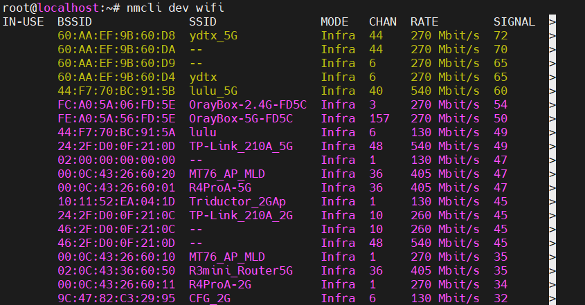
- Use the nmcli command to connect to a scanned Wi-Fi
- Change wifi_name to the name of the Wi-Fi hotspot you want to connect to
- Change wifi_passwd to the password of the Wi-Fi hotspot you want to connect to
armsom@armsom:~$ sudo nmcli dev wifi connect "wifi_name" password "wifi_password"
Device 'wlan0' successfully activated with '31dbde81-1528-4d2b-839b-422cf88cb7d4'.
- You can check the Wi-Fi IP address using the 'ip addr show wlan0' command
armsom@armsom:~$ ip addr show wlan0
4: wlan0: <BROADCAST,MULTICAST,UP,LOWER_UP> mtu 1500 qdisc mq state UP group default qlen 1000
    link/ether 0c:cd:d0:e0:96:d3 brd ff:ff:ff:ff:ff:ff
    inet 192.168.1.205/24 brd 192.168.1.255 scope global dynamic noprefixroute wlan0
       valid_lft 43029sec preferred_lft 43029sec
    inet6 fd45:d3b4:e549::468/128 scope global dynamic noprefixroute
       valid_lft 43028sec preferred_lft 43028sec
    inet6 fd45:d3b4:e549:0:20df:5d70:a5e:c43c/64 scope global dynamic noprefixroute
       valid_lft 5229sec preferred_lft 2529sec
    inet6 fe80::86c0:175a:be0d:28e1/64 scope link noprefixroute
       valid_lft forever preferred_lft forever
- You can use the ping command to test Wi-Fi network connectivity, and you can stop it by pressing Ctrl+C.
armsom@armsom:~$ sudo ping -I wlan0 www.baidu.com
PING www.wshifen.com (103.235.46.115) from 192.168.1.205 wlan0: 56(84) bytes of data.
64 bytes from 103.235.46.115 (103.235.46.115): icmp_seq=1 ttl=47 time=193 ms
64 bytes from 103.235.46.115 (103.235.46.115): icmp_seq=4 ttl=47 time=161 ms
64 bytes from 103.235.46.115 (103.235.46.115): icmp_seq=5 ttl=47 time=169 ms
64 bytes from 103.235.46.115 (103.235.46.115): icmp_seq=6 ttl=47 time=162 ms
^C
--- www.wshifen.com ping statistics ---
6 packets transmitted, 4 received, 33.3333% packet loss, time 5047ms
rtt min/avg/max/mdev = 160.909/171.260/193.269/13.133 ms
6.After using Wi-Fi, if you want to disconnect, you can run the following command, where wifi_name is the name of the Wi-Fi you're connected to.
armsom@armsom:~$ sudo nmcli con down "wifi_name"
Connection 'wifi_name' successfully deactivated (D-Bus active path: /org/freedesktop/NetworkManager/ActiveConnection/3)
The server edition image connects through a graphical interface WIFI
- There are three ways to log in to a Linux system
- If the development board is connected to a network cable, you can log in to the Linux system remotely via SSH.
- If the development board has a debug serial port connected, you can use a serial terminal to log in to the Linux system (please use MobaXterm for the serial software, minicom cannot display the graphical interface).
- If the development board is connected to an HDMI monitor, you can log in to the Linux system through the terminal displayed on HDMI.
- Type the command 'nmtui' in the command line to open the Wi-Fi connection interface.

armsom@armsom:~$ sudo nmtui
- Select 'Activate a connect' and press Enter
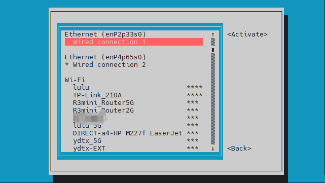
- Choose the Wi-Fi hotspot you want to connect to and enter the password. Once connected, a '*' will appear in front of the Wi-Fi name.
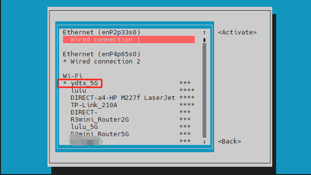
- You can check the Wi-Fi IP address using the 'ip addr show wlan0' command
armsom@armsom:~$ ip addr show wlan0
4: wlan0: <BROADCAST,MULTICAST,UP,LOWER_UP> mtu 1500 qdisc mq state UP group default qlen 1000
    link/ether 0c:cd:d0:e0:96:d3 brd ff:ff:ff:ff:ff:ff
    inet 192.168.1.205/24 brd 192.168.1.255 scope global dynamic noprefixroute wlan0
       valid_lft 43029sec preferred_lft 43029sec
    inet6 fd45:d3b4:e549::468/128 scope global dynamic noprefixroute
       valid_lft 43028sec preferred_lft 43028sec
    inet6 fd45:d3b4:e549:0:20df:5d70:a5e:c43c/64 scope global dynamic noprefixroute
       valid_lft 5229sec preferred_lft 2529sec
    inet6 fe80::86c0:175a:be0d:28e1/64 scope link noprefixroute
       valid_lft forever preferred_lft forever
- You can use the ping command to test Wi-Fi network connectivity, and you can stop it by pressing Ctrl+C.
armsom@armsom:~$ sudo ping -I wlan0 www.baidu.com
PING www.wshifen.com (103.235.46.115) from 192.168.1.205 wlan0: 56(84) bytes of data.
64 bytes from 103.235.46.115 (103.235.46.115): icmp_seq=1 ttl=47 time=193 ms
64 bytes from 103.235.46.115 (103.235.46.115): icmp_seq=4 ttl=47 time=161 ms
64 bytes from 103.235.46.115 (103.235.46.115): icmp_seq=5 ttl=47 time=169 ms
64 bytes from 103.235.46.115 (103.235.46.115): icmp_seq=6 ttl=47 time=162 ms
^C
--- www.wshifen.com ping statistics ---
6 packets transmitted, 4 received, 33.3333% packet loss, time 5047ms
rtt min/avg/max/mdev = 160.909/171.260/193.269/13.133 ms
Testing methods for the desktop version image
- Click the network setup icon in the top right corner of the desktop [Available Network]. When testing Wi-Fi, please don’t plug in an Ethernet cable.
- After connecting to Wi-Fi, you can open the browser to check if you can access the internet.
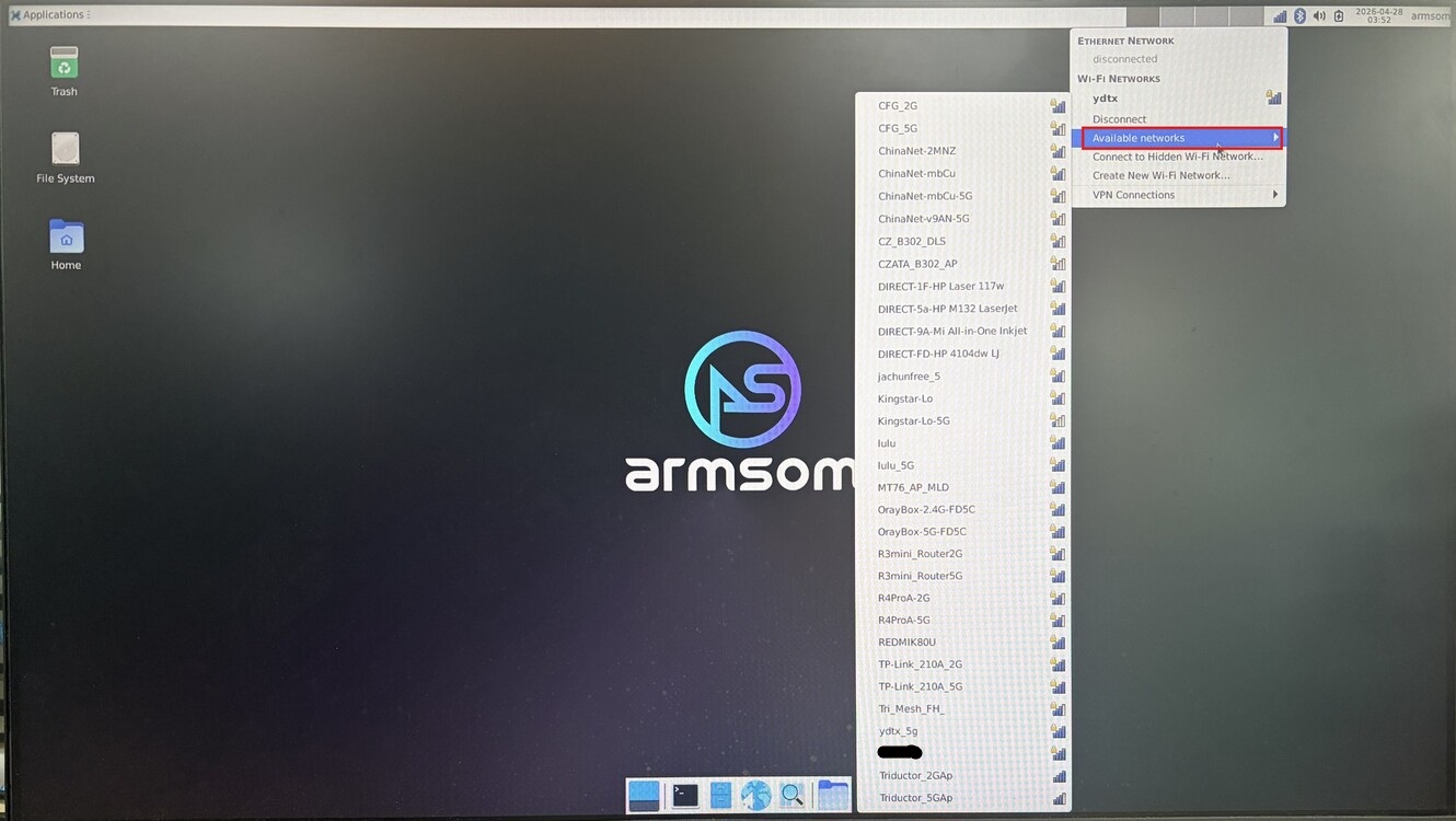
Network Settings
3.4 BT
- Before using the Bluetooth feature, let's first check if the Bluetooth device node exists to make sure Bluetooth initializes properly.
armsom@armsom:~$ hciconfig -a
hci0:   Type: Primary  Bus: UART
        BD Address: 0C:CD:D0:E0:96:D4  ACL MTU: 1021:9  SCO MTU: 255:4
        UP RUNNING
        RX bytes:918 acl:0 sco:0 events:71 errors:0
        TX bytes:5480 acl:0 sco:0 commands:71 errors:0
        Features: 0xbf 0xee 0xcd 0xfe 0xd8 0x3f 0x7b 0x87
        Packet type: DM1 DM3 DM5 DH1 DH3 DH5 HV1 HV3
        Link policy: RSWITCH SNIFF
        Link mode: PERIPHERAL ACCEPT
        Name: 'armsom'
        Class: 0x7c0000
        Service Classes: Rendering, Capturing, Object Transfer, Audio, Telephony
        Device Class: Miscellaneous,
        HCI Version: 5.2 (0xb)  Revision: 0x14
        LMP Version: 5.2 (0xb)  Subversion: 0x14
        Manufacturer: RivieraWaves S.A.S (96)
- Next, you can use bluetoothctl to connect Bluetooth.
root@localhost:/# bluetoothctl
Agent registered
1. Enable Bluetooth controller
[bluetooth]# power on
Changing power on succeeded
2. Set the controller to be discoverable
[bluetooth]# discoverable on
Changing discoverable on succeeded
[CHG] Controller 0C:CD:D0:E0:96:D4 Discoverable: yes
3. Set the controller to pairable
[bluetooth]# pairable on
Changing pairable on succeeded
4. Turn on Bluetooth device scanning
[bluetooth]# scan on
Discovery started
[NEW] Device 53:18:0C:5D:37:D7 53-18-0C-5D-37-D7
[CHG] Device 5E:16:CF:E1:CF:8A RSSI: -79
[NEW] Device 24:2A:EA:61:0F:28 Donleon  # Jot down the MAC address of the device you want to connect
[NEW] Device 20:45:30:42:40:8A V9
5. Turn off scanning
[bluetooth]# scan off
Discovery stopped
[CHG] Device 24:2A:EA:61:0F:28 RSSI is nil
[CHG] Controller 0C:CD:D0:E0:96:D4 Discovering: no
6. Set this device as a trusted device
[bluetooth]# trust 24:2A:EA:61:0F:28
[CHG] Device 24:2A:EA:61:0F:28 Trusted: yes
Changing 24:2A:EA:61:0F:28 trust succeeded
7. Pair with the device via MAC address
[bluetooth]# pair 24:2A:EA:61:0F:28
Attempting to pair with 24:2A:EA:61:0F:28
[CHG] Device 24:2A:EA:61:0F:28 Connected: yes
Request confirmation
[agent] Confirm passkey 514608 (yes/no): yes     # Enter yes here, and you also need to confirm the pairing on your phone
[CHG] Device 24:2A:EA:61:0F:28 ServicesResolved: yes
[CHG] Device 24:2A:EA:61:0F:28 Paired: yes
Pairing successful    # When it shows pairing successful here, we can exit (might need to wait a bit)
8. Connect Bluetooth device
[bluetooth]# connect 24:2A:EA:61:0F:28
Attempting to connect to 24:2A:EA:61:0F:28
[CHG] Device 24:2A:EA:61:0F:28 Connected: yes
Connection successful
[CHG] Device 24:2A:EA:61:0F:28 ServicesResolved: yes  # Just show that the connection is successful here
9. View paired devices
[Donleon]# devices
Device 24:2A:EA:61:0F:28 Donleon
10. Check the details of a device
[Donleon]# info 24:2A:EA:61:0F:28
11. Remove a device
[Donleon]# remove 24:2A:EA:61:0F:28
12. Exit
[Donleon]# exit
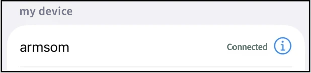
Check that your phone is paired with the development board in the Bluetooth settings:
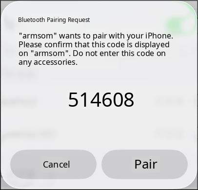
After a successful connection, it shows connected on the phone:
3.5 HDMI&DP
There are two ways to connect the Sige7s to an HDMI or DP monitor:
| Onboard interface | HDMI out | DP out |
|---|---|---|
| Resolution | 8Kp60 | 4Kp60 |
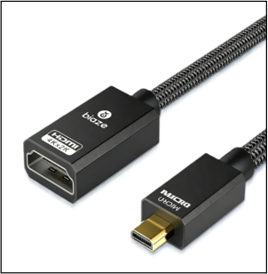
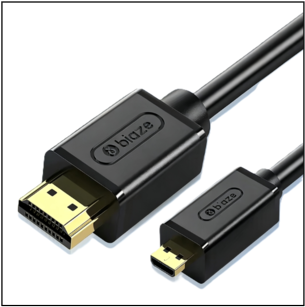
1. Use a Micro HDMI cable to connect the HDMI out port of the Sige7s and the HDMI monitor
Use one Micro HDMI to HDMI bus cable (requires an additional dual HDMI cable).
Use a Micro HDMI to HDMI public cable (can connect directly to HDMI screens)
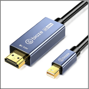
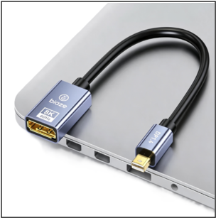
2. Use a Mini DP cable to connect the Sige7s's DP out port and the HDMI monitor or DP monitor:
Using one active Mini DP to HDMI male cable (can connect directly to HDMI screen)
Use one Mini DP to DP bus (requires an additional dual DP cable)
3. After starting the Linux system, if the monitor outputs images, it means HDMI and DP ports are working normally
- Many laptops have HDMI ports, but their HDMI ports usually only provide output functions and do not have HDMI IN functionality, meaning they cannot display other devices' HDMI outputs on the laptop's screen.
- If HDMI does not display, please first check whether the system you are using is the desktop version; if it is the server version, only the terminal is visible
- The Mini DP to HDMI cable must be active and cannot be passive
3.6 USB
| Model | Sige7s |
|---|---|
| USB | 2x USB3.0, 2x USB2.0 |
USB ports allow you to connect a USB hub to expand the number of USB ports.
Connect a USB mouse or keyboard for testing
- Insert the USB keyboard into the Sige7s's USB port
- Connect the Sige7s to an HDMI or DP monitor
- If the mouse or keyboard works properly, the operating system means the USB port is working properly (the mouse can only be used on desktop systems).
Testing by connecting USB storage devices
- First, insert a USB drive or USB external hard drive into the USB port of the ArmSoM-Sige7s
- If you see the output of sdX by executing the following command, it means the USB drive has been successfully recognized
armsom@armsom:~$ cat /proc/partitions | grep "sd*"
major minor  #blocks  name
   8        0   30720000 sda
   8        1   30718976 sda1
- You can use the mount command to mount the USB drive into /mnt, and then you can view the files on the USB drive
armsom@armsom:~$ mkdir -p /test
armsom@armsom:~$ sudo mount /dev/sda1 /test/
mount: /test: /dev/sda1 already mounted on /test.
- After mounting, you can use the df -h command to check the USB drive's capacity usage and mounting points
armsom@armsom:/$ df -h | grep "sd"
/dev/sda1        30G   64K   30G   1% /test
3.7 Micro SD card slot
The Sige7s comes with a standard microSD card slot, mainly used as a system boot disk or for expanding storage space.
When using an SD card as the system boot disk, just insert the prepared SD boot card into the Micro SD card slot before powering on, then power on. The Sige7s will prioritize booting from the SD card.
When using an SD card to expand storage space, you can follow these steps. First, check the insertion log of the SD card:
armsom@armsom:~$ [  293.228591] mmc_host mmc1: Bus speed (slot 0) = 148500000Hz (slot req 150000000Hz, actual 148500000HZ div = 0)
[  293.309039] dwmmc_rockchip fe2c0000.mmc: Successfully tuned phase to 155
[  293.309114] mmc1: new ultra high speed SDR104 SDHC card at address 0001
[  293.310505] mmcblk1: mmc1:0001 ASTC 7.44 GiB
[  293.326321]  mmcblk1: p1 p2
From the output information, it can be seen that the system has recognized the inserted SD card (mmcblk1, capacity 7.44 GiB, partitions p1 and p2), and then we confirm the SD card device information
armsom@armsom:~$ sudo fdisk -l /dev/mmcblk1
Disk /dev/mmcblk1: 7.44 GiB, 7990149120 bytes, 15605760 sectors
Units: sectors of 1 * 512 = 512 bytes
Sector size (logical/physical): 512 bytes / 512 bytes
I/O size (minimum/optimal): 512 bytes / 512 bytes
Disklabel type: gpt
Disk identifier: BDFDC9CF-2FC3-46BB-AF10-C9DF254BB1E2

Device           Start      End  Sectors  Size Type
/dev/mmcblk1p1   32768  1081343  1048576  512M Linux extended boot
/dev/mmcblk1p2 1081344 15605726 14524383  6.9G Linux filesystem
You can see the file system partition is /dev/mmcblk1p2. Next, we attach our SD card as follows
armsom@armsom:~$ sudo mkdir -p /mnt/sdcard
armsom@armsom:~$ sudo mount /dev/mmcblk1p2 /mnt/sdcard
[  491.938107] EXT4-fs (mmcblk1p2): recovery complete
[  491.939897] EXT4-fs (mmcblk1p2): mounted filesystem with ordered data mode. Quota mode: disabled.
mount: (hint) your fstab has been modified, but systemd still uses
       the old version; use 'systemctl daemon-reload' to reload.
armsom@armsom:~$ df -h /mnt/sdcard
Filesystem      Size  Used Avail Use% Mounted on
/dev/mmcblk1p2  6.8G  6.6G     0 100% /mnt/sdcard
armsom@armsom:~$ cd /mnt/sdcard/
armsom@armsom:/mnt/sdcard$ ls
bin   dev  home  lost+found  mnt  proc  run   snap  swapfile  tmp  var
boot  etc  lib   media       opt  root  sbin  srv   sys       usr
3.8 Audio
1. Check the sound card in the system.
armsom@armsom:~$ aplay -l
**** List of PLAYBACK Hardware Devices ****
card 0: rockchipdp0 [rockchip-dp0], device 0: rockchip-dp0 spdif-hifi-0 [rockchip-dp0 spdif-hifi-0]
  Subdevices: 1/1
  Subdevice #0: subdevice #0
card 1: rockchiphdmi0 [rockchip-hdmi0], device 0: rockchip-hdmi0 i2s-hifi-0 [rockchip-hdmi0 i2s-hifi-0]
  Subdevices: 1/1
  Subdevice #0: subdevice #0
card 2: rockchipes8316c [rockchip,es8316-codec], device 0: dailink-multicodecs ES8316 HiFi-0 [dailink-multicodecs ES8316 HiFi-0]
  Subdevices: 1/1
  Subdevice #0: subdevice #0
Among the listed sound card information, card 2: rockchipes8316c is the onboard es8316 audio codec, used for the 3.5mm headphone jack input (microphone) and output (audio playback).
2. Enable audio services
Before testing recording and playback, we first run the following command to automate audio configuration
armsom@armsom:~$ sudo systemctl start es8316-audio-setup
3. Record audio
This feature requires the headphones to support microphone functionality and record audio using the arecord command.
armsom@armsom:~$ arecord -D hw:2,0 -f S16_LE -r 44100 -c 2 -d 5 /tmp/record.wav
Recording WAVE '/tmp/record.wav' : Signed 16 bit Little Endian, Rate 44100 Hz, Stereo
4. Play audio
armsom@armsom:~$ aplay -D hw:2,0 /tmp/record.wav
Playing WAVE '/tmp/record.wav' : Signed 16 bit Little Endian, Rate 44100 Hz, Stereo
3.9 40 PIN
Sige offers a 40-pin GPIO socket compatible with most sensor applications on the market.
wiring-armbian method
Download the wiringOP code to the development board. wiring-armbian
- After downloading the wiringOP code, first compile and install it, then execute the following command:
armsom@armsom:/$ cd wiring-armbian/
armsom@armsom:/wiring-armbian$ ./build clean
armsom@armsom:/wiring-armbian$ ./build
- After compilation, the output of the test gpio readall command is as follows
 armsom@armsom:/wiring-armbian$ gpio readall
 +------+-----+----------+--------+---+  ArmSoM-Sige7s +---+--------+----------+-----+------+
 | GPIO | wPi |   Name   |  Mode  | V | Physical | V |  Mode  | Name     | wPi | GPIO |
 +------+-----+----------+--------+---+----++----+---+--------+----------+-----+------+
 |      |     |     3.3V |        |   |  1 || 2  |   |        | 5V       |     |      |
 |   29 |   0 | I2C1_SDA |   ALT9 | 1 |  3 || 4  |   |        | 5V       |     |      |
 |   28 |   1 | I2C1_SCL |   ALT9 | 1 |  5 || 6  |   |        | GND      |     |      |
 |   47 |   2 | GPIO1_B7 |   ALT3 | 0 |  7 || 8  | 1 | ALT10  | UART2_TX | 3   | 13   |
 |      |     |      GND |        |   |  9 || 10 | 1 | ALT10  | UART2_RX | 4   | 14   |
 |  128 |   5 | GPIO4_A0 |     IN | 0 | 11 || 12 | 1 | IN     | GPIO1_A7 | 6   | 39   |
 |  129 |   7 | GPIO4_A1 |     IN | 0 | 13 || 14 |   |        | GND      |     |      |
 |  130 |   8 | GPIO4_A2 |     IN | 0 | 15 || 16 | 1 | ALT10  | UART6_TX | 9   | 33   |
 |      |     |     3.3V |        |   | 17 || 18 | 1 | ALT10  | UART6_RX | 10  | 32   |
 |   43 |  11 |  SPI0_TX |     IN | 0 | 19 || 20 |   |        | GND      |     |      |
 |   42 |  12 |  SPI0_RX |     IN | 0 | 21 || 22 | 1 | IN     | GPIO1_B0 | 13  | 40   |
 |   44 |  14 | SPI0_CLK |     IN | 1 | 23 || 24 | 1 | IN     | SPI0_CS0 | 15  | 45   |
 |      |     |      GND |        |   | 25 || 26 | 1 | IN     | SPI0_CS1 | 16  | 46   |
 |  136 |  17 | I2C6_SDA |   ALT9 | 1 | 27 || 28 | 1 | ALT9   | I2C6_SCL | 18  | 137  |
 |  131 |  19 | GPIO4_A3 |     IN | 0 | 29 || 30 |   |        | GND      |     |      |
 |  132 |  20 | GPIO4_A4 |     IN | 0 | 31 || 32 | 1 | ALT11  | PWM2     | 21  | 105  |
 |  133 |  22 | GPIO4_A5 |     IN | 0 | 33 || 34 |   |        | GND      |     |      |
 |  134 |  23 | GPIO4_A6 |     IN | 0 | 35 || 36 | 1 | IN     | GPIO4_B2 | 24  | 138  |
 |  135 |  25 | GPIO4_A7 |     IN | 0 | 37 || 38 | 1 | IN     | GPIO4_B3 | 26  | 139  |
 |      |     |      GND |        |   | 39 || 40 | 1 | IN     | GPIO4_C3 | 27  | 115  |
 +------+-----+----------+--------+---+----++----+---+--------+----------+-----+------+
 | GPIO | wPi |   Name   |  Mode  | V | Physical | V |  Mode  | Name     | wPi | GPIO |
 +------+-----+----------+--------+---+  ArmSoM-Sige7s +---+--------+----------+-----+------+
- Set the GPIO port as output mode, where the third parameter requires the WPI index corresponding to the pin input
armsom@armsom:/wiring-armbian$ gpio mode 5 out
- Read the current level status of the corresponding pin
armsom@armsom:/wiring-armbian$ gpio read 5
0
- Set the GPIO port output to a high level. After setting, you can use a multimeter to measure the voltage at the pins. If it is 3.3V, it means the high level setting was successful
armsom@armsom:/wiring-armbian$ gpio write 5 1
armsom@armsom:/wiring-armbian$ gpio read 5
1
- Set the GPIO port output to low. After setting, you can use a multimeter to measure the voltage on the pins. If it is 0V, it means the low level was set successfully
armsom@armsom:/wiring-armbian$ gpio write 5 0
armsom@armsom:/wiring-armbian$ gpio read 5
0
- The other pin settings are similar; just change the wPi serial number to match the pin's serial number
3.10 RGB LED
The Sige7s has a user (green light) and a power indicator (red light).
User light By default, it is turned off and can be controlled by the user.
Power indicator light By default, its always-on mode means the system is running normally.
User lights can be controlled via command
armsom@armsom:~$ echo 1 | sudo tee /sys/class/leds/led2-green-usr/brightness (Light up)
armsom@armsom:~$ echo 0 | sudo tee /sys/class/leds/led2-green-usr/brightness (Close)
armsom@armsom:~$ echo heartbeat | sudo tee /sys/class/leds/led2-green-usr/trigger (Heartbeat light)
3.12 RTC
- The Sige7s integrates an RTC clock chip LK8563 within the board.
armsom@armsom:~$ dmesg | grep -w rtc
[    1.774649] rtc-hym8563 6-0051: rtc information is invalid
[    1.783043] rtc-hym8563 6-0051: registered as rtc0
[    1.784043] rtc-hym8563 6-0051: setting system clock to 2021-01-01T12:00:00 UTC (1609502400)
- Find rtc0, then use the following command to set the system time and sync to rtc0.
# Read the current time from the RTC chip
armsom@armsom:~$ sudo hwclock -r -f /dev/rtc0
2026-04-28 04:10:12.869672+08:00

# Check the system's current time
armsom@armsom:~$ date
Tue Apr 28 04:11:21 AM CST 2026

# Set system time
armsom@armsom:~$ sudo date -s "2026-07-13 10:30:00"
Mon Jul 13 10:30:00 AM CST 2026

# Write the system's current time to the RTC
armsom@armsom:~$ sudo hwclock -w -f /dev/rtc0

# Then read the current time from the RTC chip
armsom@armsom:~$ sudo hwclock -r -f /dev/rtc0
2026-07-13 10:30:58.518923+08:00
- Turn off the RTC battery (shut down the power), wait for 10 minutes or longer, then restart the Sige7s and check the RTC time.
# Because the RTC lost power and the data was lost, when I use the hwclock command to check the RTC clock, it goes back to the previous initial date.
armsom@armsom:~$ sudo hwclock -r -f /dev/rtc0
2026-04-28 03:50:21.479385+08:00
3.13 MIPI-CSI
ArmSoM-Sige7s is compatible with the following two imx219 cameras:
Connect the imx219 camera to the development board's MIPI-CSI interface, as shown in the picture:
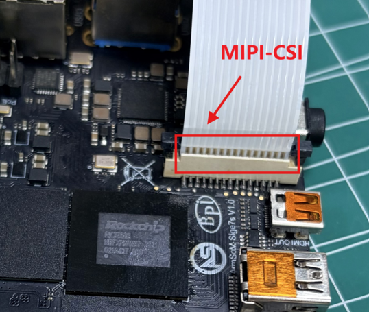
- The system has the camera function turned off by default. If you want to turn it on, you need to follow the steps below to enable the MIPI-CSI camera overlay.
root@armsom:~# vi /boot/uEnv/uEnvarmsom-sige7s.txt
Find this part, and just uncomment the line below to enable the overlay:
#dtoverlay=/dtb/overlay/rk3588-armsom-sige7s-camera-imx219-overlay.dtbo
root@armsom:~#  # Save and restart after exiting
- After opening the camera settings, let's first check if the driver is loading properly.
root@armsom:~# dmesg | grep imx219
[    2.045457] platform csi2-dphy0: Fixed dependency cycle(s) with /i2c@feca0000/imx219@10
[    2.333293] imx219 8-0010: module_facing == front
[    2.333306] imx219 8-0010: module_name == GEIR180089
[    2.333316] imx219 8-0010: len_name == LG500627G
[    2.333334] imx219 8-0010: Looking up VANA-supply from device tree
[    2.336240] imx219 8-0010: Looking up VDIG-supply from device tree
[    2.336324] imx219 8-0010: Looking up VDDL-supply from device tree
[    2.345369] imx219 8-0010: imx219_init_controls666
[    2.345391] imx219 8-0010: Consider updating driver imx219 to match on endpoints
[    2.345406] rockchip-csi2-dphy csi2-dphy0: dphy0 matches m01_f_imx219 8-0010:bus type 5
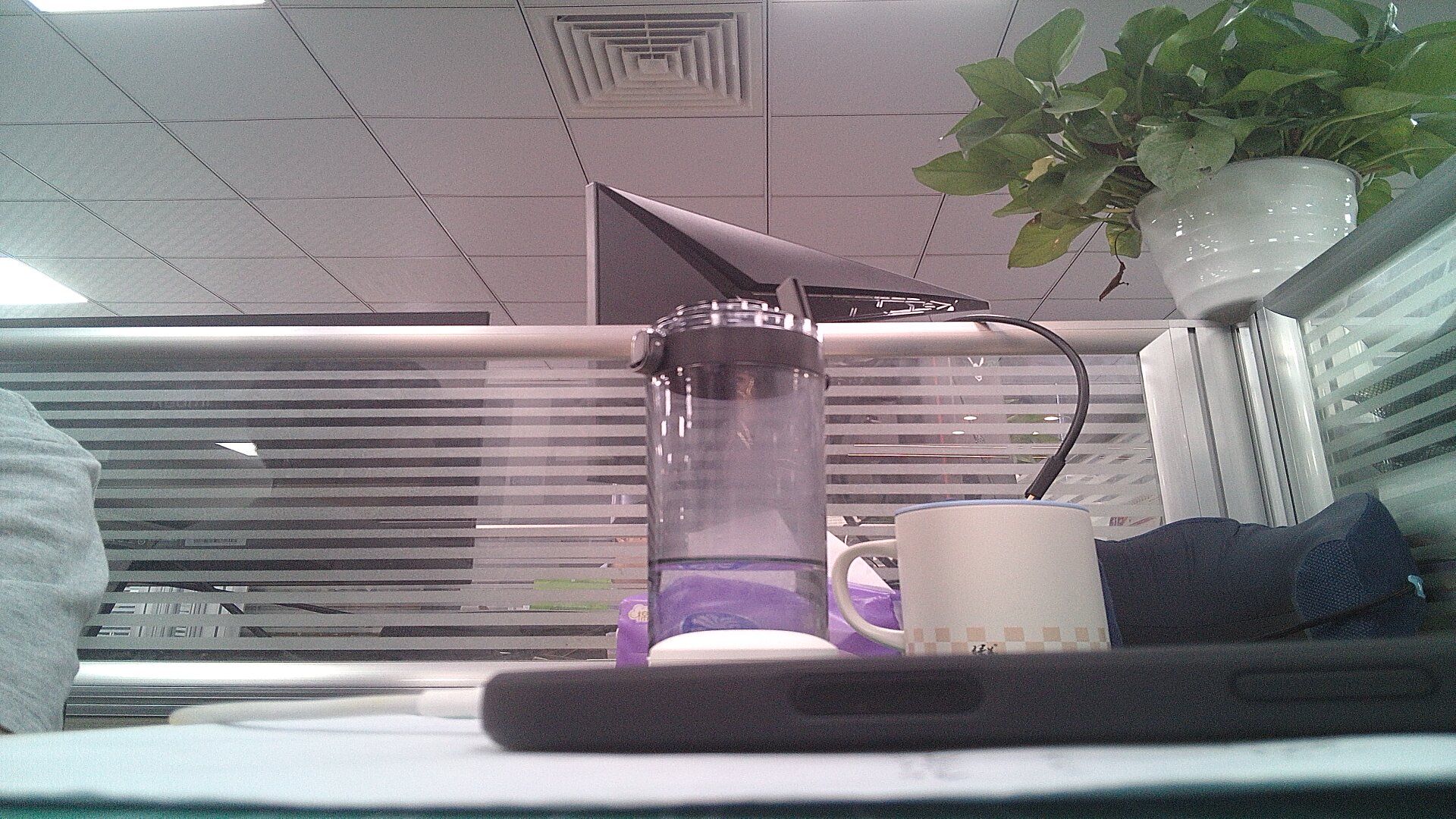
- After confirming the driver is loaded, run the following command to take a photo or record a video
- take a photo
root@armsom:~# gst-launch-1.0 v4l2src device=/dev/video11 io-mode=4 ! videoconvert ! video/x-raw,format=NV12,width=1920,height=1080 ! jpegenc ! multifilesink location=photo.jpg
- record a video
root@armsom:~# gst-launch-1.0 v4l2src num-buffers=512 device=/dev/video11 io-mode=4 ! videoconvert ! video/x-raw, format=NV12, width=1920, height=1080, framerate=30/1 ! tee name=t ! queue ! mpph264enc ! queue ! h264parse ! mpegtsmux ! filesink location=/root/video.mp4
3.14 MIPI DSI
ArmSoM-Sige7s MIPI DSI interface compatible with the wareshare (compatible with Raspberry Pi) 7-inch screen, purchase link:
https://item.taobao.com/item.htm?id=646210381978
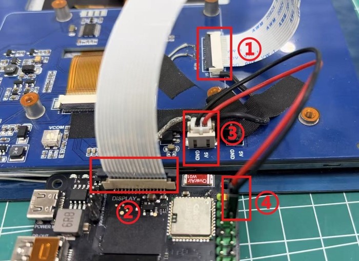
1. Connect the flex cable as shown in the diagram below
DSI connector
Use 15 channels of flat flexible cable (FFC) to connect ① the screen FFC connector and ② the SIGE7s MIPI DSIGPIO pin headers
Use a GPIO power cable to connect the screen ③ at the 5V & GND interface and ④ the 5V & GND pins in the 40pin Sige7s, such as pin 4 and pin 6 (if pin 6 is used here, the serial port GND pin needs to be connected to other GND pins).
2. By default, the system turns off the MIPI-DSI screen. To turn it on, follow these steps to enable the LCD display overlay
armsom@armsom:~$ sudo vi /boot/uEnv/uEnvarmsom-sige7s.txt
#Find this part and just uncomment the line below to enable the overlay:
#dtoverlay=/dtb/overlay/rk3588-armsom-sige7s-display-800x480-7hd-overlay.dtbo
armsom@armsom:~$ sudo reboot  #Save and restart after exiting
After overlay is activated, observe whether the LCD screen displays and enters the desktop
3.15 CPU/GPU/NPU/DDR
Below are the methods for setting the CPU, GPU, NPU DDR, frequency fixing, and performance mode settings for the ArmSoM-Sige7s
Fixed frequency
CPU fixed frequency
The ArmSoM-Sige7s CPUs consist of 4 A55 + 4 A76 processors, managed separately in 3 groups. The nodes are:
armsom@armsom:~$ ls /sys/devices/system/cpu/cpufreq/policy0  (Corresponding to 4 A55:CPU0-3)
affected_cpus               related_cpus                   scaling_max_freq
cpuinfo_cur_freq            scaling_available_frequencies  scaling_min_freq
cpuinfo_max_freq            scaling_available_governors    scaling_setspeed
cpuinfo_min_freq            scaling_cur_freq               stats
cpuinfo_transition_latency  scaling_driver
ondemand                    scaling_governor

armsom@armsom:~$ ls /sys/devices/system/cpu/cpufreq/policy4  (Corresponding to 2 A76:CPU4-5)
affected_cpus               related_cpus                   scaling_max_freq
cpuinfo_cur_freq            scaling_available_frequencies  scaling_min_freq
cpuinfo_max_freq            scaling_available_governors    scaling_setspeed
cpuinfo_min_freq            scaling_cur_freq               stats
cpuinfo_transition_latency  scaling_driver
ondemand                    scaling_governor

armsom@armsom:~$ ls /sys/devices/system/cpu/cpufreq/policy6   (Corresponding to 2 A76:CPU6-7)
affected_cpus               related_cpus                   scaling_max_freq
cpuinfo_cur_freq            scaling_available_frequencies  scaling_min_freq
cpuinfo_max_freq            scaling_available_governors    scaling_setspeed
cpuinfo_min_freq            scaling_cur_freq               stats
cpuinfo_transition_latency  scaling_driver
ondemand                    scaling_governor

armsom@armsom:~$ cat /sys/devices/system/cpu/cpufreq/policy6/scaling_available_frequencies # Get the current CPU-supported frequency points
408000 600000 816000 1008000 1200000 1416000 1608000 1800000 2016000 2208000 2256000
armsom@armsom:~$ cat /sys/devices/system/cpu/cpufreq/policy6/scaling_available_governors # Get the CPU's running mode
interactive conservative ondemand userspace powersave performance schedutil
# The default is the on-demand frequency scaling mode: ondemand (if you want to restore it, just set it to this mode)
Note: The following operations should be performed as the root user
Set manual frequency
root@armsom:~$ cat /sys/devices/system/cpu/cpufreq/policy6/cpuinfo_cur_freq
600000   # Check current frequency
root@armsom:~$ echo userspace > /sys/devices/system/cpu/cpufreq/policy6/scaling_governor  # Manual fixed-frequency mode:userspace
root@armsom:~$ echo 1608000 > /sys/devices/system/cpu/cpufreq/policy6/scaling_setspeed  # Set the frequency to 1,608,000
root@armsom:~$ cat /sys/devices/system/cpu/cpufreq/policy6/cpuinfo_cur_freq    # Check if the setup was successful
1608000
The other two CPU groups are configured similarly; just operate the corresponding node.
GPU fixed frequency
GPU node path
root@armsom:~$ ls /sys/class/devfreq/fb000000.gpu
available_frequencies  governor  name              target_freq
available_governors    load      polling_interval  timer
cur_freq               max_freq  power             trans_stat
device                 min_freq  subsystem         uevent
root@armsom:~$ cat /sys/class/devfreq/fb000000.gpu/available_frequencies  # Get GPU-supported frequency bands
1000000000 900000000 800000000 700000000 600000000 500000000 400000000 300000000
root@armsom:~$ cat /sys/class/devfreq/fb000000.gpu/available_governors  # Get the mode in which the GPU is running
rknpu_ondemand dmc_ondemand userspace powersave performance simple_ondemand
The default is the general on-demand frequency scaling mode: simple_ondemand (to restore, just set it to this mode).
Set manual frequency
root@armsom:~$ cat /sys/class/devfreq/fb000000.gpu/cur_freq # Check current frequency
300000000
root@armsom:~$ echo userspace > /sys/class/devfreq/fb000000.gpu/governor  # Manual fixed-frequency mode: userspace
root@armsom:~$ echo 600000000 > /sys/class/devfreq/fb000000.gpu/userspace/set_freq  # Set the frequency to 600,000,000
root@armsom:~$ cat /sys/class/devfreq/fb000000.gpu/cur_freq  # Check if it's set up successfully
600000000
NPU fixed frequency
NPU node path
root@armsom:~$ ls /sys/class/devfreq/fdab0000.npu/
available_frequencies  device    max_freq  power        trans_stat
available_governors    governor  min_freq  subsystem    uevent
cur_freq               load      name      target_freq
root@armsom:~$ cat /sys/class/devfreq/fdab0000.npu/available_frequencies  # Get the frequency bands supported by the NPU
300000000 400000000 500000000 600000000 700000000 800000000 900000000 1000000000
root@armsom:~$ cat /sys/class/devfreq/fdab0000.npu/available_governors # Get the mode in which the NPU is running
rknpu_ondemand dmc_ondemand userspace powersave performance simple_ondemand
The default is the on-demand frequency mode: rknpu_ondemand (to restore, just set it to this mode).
Set manual frequency
root@armsom:~$ cat /sys/class/devfreq/fdab0000.npu/cur_freq # Check current NPU frequency
1000000000
root@armsom:~$ echo userspace > /sys/class/devfreq/fdab0000.npu/governor # Manual Frequency Mode: userspace
root@armsom:~$ echo 600000000 > /sys/class/devfreq/fdab0000.npu/userspace/set_freq # Set the frequency to 600,000,000
root@armsom:~$ cat /sys/class/devfreq/fdab0000.npu/cur_freq  # Check if it's set up successfully
600000000
root@armsom:~$ cat /sys/kernel/debug/rknpu/load # Check the NPU load
NPU load:  Core0:  0%, Core1:  0%, Core2:  0%,
DDR fixed frequency
DDR node path
root@armsom:~$ ls /sys/class/devfreq/dmc/
available_frequencies  downdifferential  min_freq   system_status  upthreshold
available_governors    governor          name       target_freq
cur_freq               load              power      trans_stat
device                 max_freq          subsystem  uevent
root@armsom:~$ cat /sys/class/devfreq/dmc/available_frequencies # Get DDR-supported frequency bands
528000000 1068000000 1560000000 2112000000
root@armsom:~$ cat /sys/class/devfreq/dmc/available_governors # Get the mode in which DDR is running
rknpu_ondemand dmc_ondemand userspace powersave performance simple_ondemand
The default is the on-demand frequency mode: dmc_ondemand (to restore it, just set it to this mode).
Set manual frequency
root@armsom:~$ cat /sys/class/devfreq/dmc/cur_freq # Check current frequency
528000000
root@armsom:~$ echo userspace > /sys/class/devfreq/dmc/governor # Manual fixed frequency mode: userspace
root@armsom:~$ echo 1560000000 > /sys/class/devfreq/dmc/userspace/set_freq  # Set the frequency to 1560000000
root@armsom:~$ cat /sys/class/devfreq/dmc/cur_freq   # Check if the setup was successful
1560000000
Performance Mode
root@armsom:~$ echo performance > /sys/devices/system/cpu/cpufreq/policy6/scaling_governor
root@armsom:~$ echo performance > /sys/class/devfreq/fb000000.gpu/governor
root@armsom:~$ echo performance > /sys/class/devfreq/dmc/governor
root@armsom:~$ echo performance > /sys/class/devfreq/fdab0000.npu/governor
Product Certificate
CE / FCC / RoHS
Supply Statement
The ArmSoM-Sige7s will be produced at least until January 2034.
Purchase Samples
ArmSoM online shop:
ArmSoM Aliexpress online shop:
ArmSoM Taobao shop:
OEM&ODM, please contact: sales@armsom.org
Notes
- Before handling the device, please ensure you wear an anti-static wrist strap or take electrostatic discharge measures to prevent damage to the development board.
- Assembly should be performed in an electrostatic-safe environment, avoiding operations in dry and low-humidity conditions.
- When not in use, store the device in an anti-static bag and keep it in a suitably temperature-controlled, low-humidity environment to prevent static electricity buildup.
- When handling the device, avoid friction or collisions to prevent the generation of static electricity that could cause damage.
- When holding the device, try to avoid direct contact with the chips on the mainboard to prevent static damage.
- Do not plug or unplug wires or other devices while the device is operating to avoid damage from electrical surges.
- When connecting or disconnecting the GPIO/MIPI expansion interfaces, make sure to turn off the power and disconnect the power cable to prevent damage from electrical current.
Without effective cooling measures, the surface temperature of the main chip may exceed 60 degrees. When handling the device, please avoid direct contact with the SoC and surrounding power inductors to prevent burns. Ensure that the environment is well-ventilated during operation to prevent localized heat buildup, which could lead to overheating. Additionally, do not place the device in direct sunlight. It is recommended to choose between the official cooling fan, heat sink, or third-party cooling kits based on specific usage conditions to ensure optimal cooling performance.