Forge1 Product Introduction
Let’s get to know Forge1 in 5 minutes.
Overview
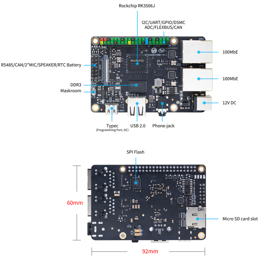
Forge1 is an industrial-grade product powered by the RK3506J triple-core Cortex-A7 application processor. Operating within a temperature range of -40℃ to 85℃, it is specifically designed for industrial gateways, HMIs (Human-Machine Interfaces), PLCs (Programmable Logic Controllers), handheld POS (Point-of-Sale) devices, and home appliance display/control applications.
The embedded 2D hardware engine and display output engine minimize CPU overhead to meet demanding graphics rendering requirements.
With a comprehensive set of peripheral interfaces—including RS485, USB2, RMII (Reduced Media Independent Interface), CAN (Controller Area Network), DSMC (Digital Signal Microcontroller), Flexbus, and more—it accommodates diverse application development needs while reducing hardware complexity and development costs.

Hardware Information
Hardware Interfaces
Hardware Specifications
| Category | Specifications |
|---|---|
| SOC | |
| CPU | |
| GPU | |
| Memory | |
| Storage | |
| Networking | |
| Video Output | |
| Audio | |
| USB Interfaces | |
| 40-PIN | |
| Power Supply | |
| Buttons | |
| OS | |
| Dimensions | |
| Operating Temperature |
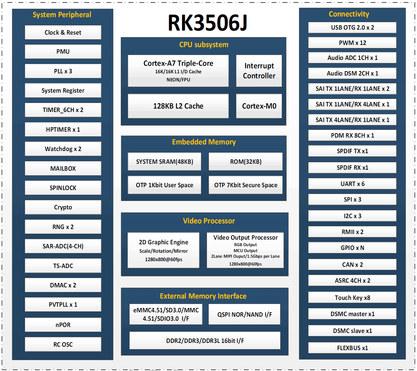
RK3506J Block Diagram
RK3506J Block Diagram
Pin Definitions
40-PIN header(2.54mm)
| GPIO Number | Function | Pin | Pin | Function | GPIO Number |
|---|---|---|---|---|---|
| +3.3V | 1 | 2 | +5.0V | ||
| 4 | RM_IO4/SAI0_SDI0/GPIO0_A4_d | 3 | 4 | +5.0V | |
| 5 | RM_IO5/SAI0_SDI1/GPIO0_A5_d | 5 | 6 | GND | |
| 59 | DSMC_SLV_RDYN/RM_IO31/UART5_RX_M1 FLEXBUS0_D0/DSMC_CSN3/VO_LCDC_D0 GPIO1_D3_d | 7 | 8 | UART0_TX RM_IO22/JTAG_TCK_M1/GPIO0_C6_u | 22 |
| GND | 9 | 10 | UART0_RX RM_IO23/JTAG_TMS_M1/GPIO0_C7_u | 23 | |
| 58 | DSMC_SLV_CSN0/RM_IO30/UART5_TX_M1 FLEXBUS0_D1/DSMC_CSN2/VO_LCDC_D1 GPIO1_D2_d | 11 | 12 | GPIO1_D1_d/DSMC_SLV_D7 RM_IO29UART5_RTSN_M1/DSM_AUD_LP_M0 FLEXBUS0_D2/DSMC_DQS1/VO_LCDC_D2 | 57 |
| 52 | DSMC_SLV_D2/FLEXBUS0_D7 DSMC_D11/VO_LCDC_D7 GPIO1_C4_d | 13 | 14 | GPIO1_C5_d DSMC_SLV_D3/FLEXBUS0_D6 DSMC_D12/VO_LCDC_D6 | 53 |
| 51 | DSMC_SLV_D1/RM_IO28/SAI2_SDO_M1 FLEXBUS1_CSN_M5/FLEXBUS0_D8 DSMC_D10/VO_LCDC_D8 GPIO1_C3_d | 15 | 16 | GPIO1_C2_d DSMC_SLV_D0/RM_IO27SAI2_SDI_M1 FLEXBUS0_CSN_M5/DSM_AUD_RP_M0 FLEXBUS0_D9/DSMC_D9/VO_LCDC_D9 | 50 |
| +3.3V | 17 | 18 | GPIO1_C1_d/DSMC_SLV_DQS0/SAI2_MCLK_M1 FLEXBUS1_CSN_M4/DSM_AUD_RN_M0 FLEXBUS0_CLK/DSMC_D8/VO_LCDC_D10 | 49 | |
| 48 | DSMC_SLV_CLK/FLEXBUS0_CSN_M4 DSMC_INT1/FLEXBUS1_CLK DSMC_RESETN/VO_LCDC_D11 GPIO1_C0_d | 19 | 20 | SARADC_IN2/GPIO4_B2_z | 138 |
| 46 | FLEXBUS0_CSN_M3/FLEXBUS0_D11 FLEXBUS1_D14/DSMC_CSN0 VO_LCDC_D13/GPIO1_B6_d | 21 | 22 | GPIO1_B7_d FLEXBUS1_CSN_M3/FLEXBUS0_D10 FLEXBUS1_D15/DSMC_RDYN/VO_LCDC_D1 | 47 |
| 44 | FLEXBUS0_CSN_M2/FLEXBUS0_D13 FLEXBUS1_D12/DSMC_D6 VO_LCDC_D15GPIO1_B4_d | 23 | 24 | GPIO1_B5_d FLEXBUS1_CSN_M2/FLEXBUS0_D12 FLEXBUS1_D13/DSMC_D7/VO_LCDC_D14 | 45 |
| GND | 25 | 26 | GPIO1_B3_d RM_IO26/SAI2_LRCK_M1FLEXBUS1_CSN_M1 FLEXBUS0_D14/FLEXBUS1_D11 DSMC_INT3/VO_LCDC_D16 | 43 | |
| 41 | RM_IO24/UART5_CTSN_M1 FLEXBUS1_CSN_M0/FLEXBUS1_D9 DSMC_CSN1/VO_LCDC_D184 GPIO1_B1_d | 27 | 28 | GPIO1_B2_d RM_IO25/SAI2_SCLK_M1FLEXBUS0_CSN_M1 FLEXBUS0_D15/FLEXBUS1_D10 DSMC_INT2/VO_LCDC_D17 | 42 |
| 40 | FLEXBUS0_CSN_M0/FLEXBUS1_D8 DSMC_D5/VO_LCDC_D19 GPIO1_B0_d | 29 | 30 | GND | |
| 38 | FLEXBUS1_D6/DSMC_D3 VO_LCDC_D21/GPIO1_A6_d | 31 | 32 | GPIO1_A7_d/FLEXBUS1_D7 DSMC_D4/VO_LCDC_D20 | 39 |
| 37 | FLEXBUS1_D5/DSMC_D2VO_LCDC_D22 GPIO1_A5_d | 33 | 34 | GND | |
| 35 | FLEXBUS1_D3/DSMC_D0/VO_LCDC_CLK GPIO1_A3_d | 35 | 36 | GPIO1_A4_d/FLEXBUS1_D4 DSMC_D1/VO_LCDC_D23 | 36 |
| 33 | DSMC_SLV_INT/DSMC_INT0 FLEXBUS1_D1/DSMC_CLKN VO_LCDC_VSYNC/GPIO1_A1_d | 37 | 38 | GPIO1_A2_d/FLEXBUS1_D2 DSMC_DQS0/VO_LCDC_HSYNC | 34 |
| GND | 39 | 40 | GPIO1_A0_d/FLEXBUS1_D0 DSMC_CLKP/VO_LCDC_DEN | 32 |
14-PIN Header(2.54mm)
| Pin | Assignment | Description | Pin | Assignment | Description |
|---|---|---|---|---|---|
| 1 | RS485_A | RS485 Differential Signal (Positive) | 2 | RS485_B | RS485 Differential Signal (Negative) |
| 3 | CAN_L | CAN Bus Differential Low | 4 | CAN_H | CAN Bus Differential High |
| 5 | GND | System Ground | 6 | GND | System Ground (Redundant Design) |
| 7 | MICIN_P | Microphone Input Positive (Differential) | 8 | MICIN_N | Microphone Input Negative (Differential) |
| 9 | MICIN_P | Microphone Input Positive (Alternate Channel) | 10 | MICIN_N | Microphone Input Negative (Alternate Channel) |
| 11 | GND | Audio Signal Ground | 12 | VBAT_RTC | RTC Battery Power Input |
| 13 | SPK_P | Speaker Output Positive (Differential Drive) | 14 | SPK_N | Speaker Output Negative (Differential Drive) |
Development Resources
SDK Source Code
Official Image
The ArmSoM team uses buildroot as the official operating system for Forge1. How to Flash Image📤
Download
The following systems have been tested and verified by ArmSoM official:
Network disk address:
Google Drive link| logo | Description | Download |
|---|---|---|
| buildroot | buildroot for Forge1: Linux Kernel 6.1, support RT-Thread 4.1, support bare metal programs, support multi-core heterogeneous AMP, Preempt-RT/Xenomai real-time patches, lightweight UI framework LVGL. | Google Drive link |
Hardware Resources
Google Drive linkUser Manual
Tools Preparation
- Power Supply (Choose either):
- DC IN 12V/1A
- Type-C 5V/2A
- System Installation (Choose either):
- Boot from onboard eMMC:
- USB Type-C data cable (to connect the Forge series device and a PC via the Type-C port for image burning).
- Boot from MicroSD/TF card:
- MicroSD/TF card (Class 10 or higher, at least 8GB SDHC) and a card reader.
Image Flashing
Interface Usage
If this is your first time using the ArmSoM-Forge1 product, please familiarize yourself with its hardware interfaces to better understand subsequent content.
| Hardware Interface | Forge1 |
|---|
Debug Serial
Connect the USB-to-TTL serial cable as shown below:
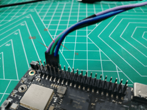
| Forge1 Pin | Connection | Serial Module |
|---|---|---|
| GND (Pin 6) | → | GND |
| TX (Pin 8) | → | RX |
| RX (Pin 10) | → | TX |
Ethernet
- Connect one end of an Ethernet cable to the Forge1's Ethernet port and the other end to a router. Ensure the network is available.
- The system will automatically assign an IP address to the Ethernet interface via DHCP on startup.
- To view the IP address in Forge1’s Linux system:
root@armsom:/# ip a
1: lo: <LOOPBACK,UP,LOWER_UP> mtu 65536 qdisc noqueue state UNKNOWN group default qlen 1000
    link/loopback 00:00:00:00:00:00 brd 00:00:00:00:00:00
    inet 127.0.0.1/8 scope host lo
       valid_lft forever preferred_lft forever
2: can0: <NOARP,ECHO> mtu 16 qdisc noop state DOWN group default qlen 10
    link/can
3: eth0: <NO-CARRIER,BROADCAST,MULTICAST,UP> mtu 1500 qdisc mq state DOWN group default qlen 1000
    link/ether 9e:06:ad:d5:e3:91 brd ff:ff:ff:ff:ff:ff
4: eth1: <BROADCAST,MULTICAST,UP,LOWER_UP> mtu 1500 qdisc mq state UP group default qlen 1000
    link/ether 7e:09:de:1d:0c:46 brd ff:ff:ff:ff:ff:ff
    inet 192.168.1.150/24 brd 192.168.1.255 scope global dynamic noprefixroute eth1
       valid_lft 43173sec preferred_lft 37773sec
- Use the
pingcommand to verify network connectivity (pressCtrl+Cto exit):
root@armsom:/# ping www.baidu.com
PING www.baidu.com (183.2.172.17): 56 data bytes
64 bytes from 183.2.172.17: seq=0 ttl=52 time=10.838 ms
...
^C
--- www.baidu.com ping statistics ---
6 packets transmitted, 6 received, 0% packet loss
USB Interface
| Model | Forge1 |
|---|---|
| USB | 1× Type-C (PD & Programming), 1× USB 2.0 HOST |
Testing USB Storage Devices
- Insert a USB flash drive or external HDD into the Forge1’s USB port.
- Verify detection with:
root@armsom:/# cat /proc/partitions | grep "sd*"
major minor  #blocks  name
   8        0  122880000 sda
- Mount the USB drive:
root@armsom:/# sudo mount /dev/sda1 /test/
- Check usage and mount point:
root@armsom:/test# df -h | grep "sd"
/dev/sda        4.7G  4.7G     0  100% /test
Audio
List Audio Devices
root@armsom:/# aplay -l
**** List of PLAYBACK Hardware Devices ****
card 0: rockchiprk730 [rockchip-rk730], device 0: dailink-multicodecs HiFi-0
Recording
arecord -D hw:0,0 -f S16_LE -t wav -c2 -r 16000 -d 3 t.wav
Playback
aplay t.wav
RTC
• Forge1 includes an LK8563S RTC IC.
• Insert a 2-pin RTC battery to power the RTC.
Verify RTC Device
root@armsom:/# dmesg | grep rtc
[    6.407133] rtc-hym8563 6-0051: registered as rtc0
Sync System Time to RTC
root@armsom:/# hwclock -r                # Read RTC time
root@armsom:/# hwclock -w                # Write system time to RTC
root@armsom:/# poweroff
Post-Reconnection Check
After reconnecting the RTC battery:
root@armsom:/# hwclock -r
2023-11-03 10:35:40.461910+00:00
root@armsom:/# date
Fri Nov 3 10:36:01 UTC 2023
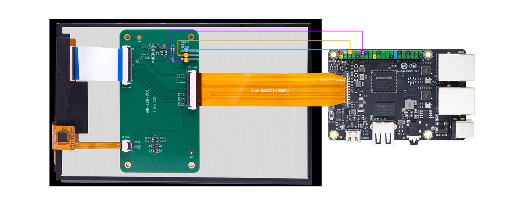
MIPI DSI
Maximum Resolution: 1280x1280@60fps.
CAN FD
List Network Interfaces
root@armsom:/# ifconfig -a
can0: <NOARP,MTU=16> ...
CAN Configuration
ip link set can0 down
ip link set can0 type can bitrate 1000000 dbitrate 3000000 fd on
ip -details link show can0
ip link set can0 up
CAN FD Testing
• Send Standard Frame:
cansend can0 123##1DEADBEEF
• Send Extended Frame:
cansend can0 00000123##1DEADBEEF
• Monitor CAN Messages:
candump can0 &
Availability
The Forge1 will remain in production until at least May 2035.
Accessories
We designed the official accessory ArmSoM-Sige to help you achieve optimal performance from your computer.

Purchase Samples
ArmSoM Official Website: https://www.armsom.org/product-page/forge1
ArmSoM Official AliExpress Store: https://aliexpress.com/item/3256807356692995.html
ArmSoM Official Taobao Store: https://item.taobao.com/item.htm?id=895906881225
For OEM & ODM, please contact: sales@armsom.org
What do others say about the Forge1?
- CNX: $23 ArmSoM Forge1 industrial SBC is powered by Rockchip RK3506J SoC
- itsfoss: ArmSoM's Forge1 Looks Like A Versatile Solution for Embedded and Multimedia Applications
- electronics-lab:ArmSoM Forge1 SBC Features Rockchip RK3506J SoC with Cortex-A7/M0 Cores for Industrial and Audio Applications
- notebookcheck:Forge1: Neue IoT-Alternative zum Raspberry Pi startet günstig
- taoofmac:The ArmSom Forge1
- Platima Tinkers: ArmSoM Forge1 and Sige7 - The best ARM SBC I have ever tested!
Notes
- Before handling the device, please ensure you wear an anti-static wrist strap or take electrostatic discharge measures to prevent damage to the development board.
- Assembly should be performed in an electrostatic-safe environment, avoiding operations in dry and low-humidity conditions.
- When not in use, store the device in an anti-static bag and keep it in a suitably temperature-controlled, low-humidity environment to prevent static electricity buildup.
- When handling the device, avoid friction or collisions to prevent the generation of static electricity that could cause damage.
- When holding the device, try to avoid direct contact with the chips on the mainboard to prevent static damage.
- Do not plug or unplug wires or other devices while the device is operating to avoid damage from electrical surges.
- When connecting or disconnecting the GPIO/MIPI expansion interfaces, make sure to turn off the power and disconnect the power cable to prevent damage from electrical current.