11. Camera Usage
MIPI-CSI (Mobile Industry Processor Interface - Camera Serial Interface) is a high-speed, low-power interface standard used to connect image sensors and processors, widely applied in mobile devices, embedded systems, and other electronic devices. MIPI-CSI provides a fast and efficient way to transmit high-resolution video and images from the camera module to the processor.
The MIPI-CSI interface consists of the following components:
- Data Lines (D0, D1, D2, etc.): These data lines are used to transmit image data from the camera to the processor.
- Clock Line (CLK): The clock line provides synchronization signals between the camera and the processor.
- MIPI-CSI Receiver (CSI-Receiver): Located on the processor, the receiver receives MIPI data and clock signals.
- MIPI-CSI Transmitter (CSI-Transmitter): Located on the camera, the transmitter sends image data to the processor.
- MIPI-CSI standards support different data rates, depending on the specific implementation (such as MIPI-CSI2 or MIPI-CSI3).
11.1 Camera Usage Example
11.1.1 Camera Pins
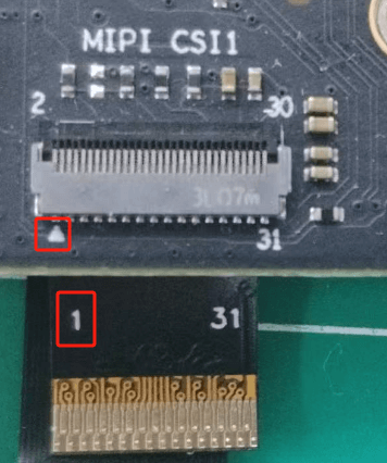
ArmSoM products with MIPI-CSI support are compatible with the ArmSoM camera-module1.
In ArmSoM products, the MIPI-CSI pin 1 connects to pin 1 of the camera module.
11.1.2 Enabling Camera Communication Interface
In the Ubuntu/debian operating system, the/boot/uEnv/uEnv. txt file is used to configure system startup parameters and device tree plugins. You can edit this file to enable or disable MIPI-CSI device tree overlays.
To check or enable MIPI-CSI related device tree overlays, follow these steps:
- View Device Tree Overlay Configuration
Open file: Open the/boot/uEnv/uEnv. txt file through the terminal, for example:
root@armsom:/home/armsom# sudo vi /boot/uEnv/uEnv.txt
Here's an example of activating armsom-sige5-camera-ov13850-cs0. To open armsom-sige5-camera-ov13850-cs0, use the following:
# CAM0
dtoverlay=/dtb/overlay/rk3576-armsom-sige5-camera-ov13850-cs0-overlay.dtbo
# CAM1
dtoverlay=/dtb/overlay/rk3576-armsom-sige5-camera-ov13850-cs1-overlay.dtbo
Remove the # before dtoverlay, after editing, save the file and exit the editor to restart the system for the configuration to take effect:
// Run sync first
armsom@armsom:/boot# sync
armsom@armsom:/boot# sudo reboot
- Q: If I power off the system directly, is there a risk of the file not being modified or the overlay system failing to start?
- A: When powering off or forcefully shutting down, there is a possibility that files may not have been synced from memory (RAM) to storage (e.g., hard drive or SSD). The operating system typically stores data in memory and writes it to disk periodically. To avoid this issue, it's recommended to run the
synccommand before shutting down to ensure all data is written to disk before powering off or shutting down.
- Verify if ArmSoM Camera-Module1 is Enabled
After enabling the armsom-camera-module1 device tree overlay and rebooting the board, once the camera module is connected and powered on, you can check the boot log.
armsom@armsom:~$ dmesg | grep ov13850
[    3.481341] platform csi2-dphy3: Fixed dependency cycle(s) with /i2c@2ac70000/ov13850_1@10
[    3.482159] platform csi2-dphy0: Fixed dependency cycle(s) with /i2c@2ac80000/ov13850@10
[    3.574146] ov13850 5-0010: driver version: 00.01.05
[    3.574179] ov13850 5-0010: Failed to get power-gpios, maybe no use
[    3.574217] ov13850 5-0010: Looking up avdd-supply from device tree
[    3.574225] ov13850 5-0010: Looking up avdd-supply property in node /i2c@2ac80000/ov13850@10 failed
[    3.574256] ov13850 5-0010: supply avdd not found, using dummy regulator
[    3.574332] ov13850 5-0010: Looking up dovdd-supply from device tree
[    3.574340] ov13850 5-0010: Looking up dovdd-supply property in node /i2c@2ac80000/ov13850@10 failed
[    3.574358] ov13850 5-0010: supply dovdd not found, using dummy regulator
[    3.574383] ov13850 5-0010: Looking up dvdd-supply from device tree
[    3.574390] ov13850 5-0010: Looking up dvdd-supply property in node /i2c@2ac80000/ov13850@10 failed
[    3.574407] ov13850 5-0010: supply dvdd not found, using dummy regulator
[    3.574433] ov13850 5-0010: could not get default pinstate
[    3.574438] ov13850 5-0010: could not get sleep pinstate
[    3.579394] ov13850 5-0010: Detected OV00d850 sensor, REVISION 0xb2
[    3.619842] ov13850 5-0010: Consider updating driver ov13850 to match on endpoints
[    3.619848] rockchip-csi2-dphy csi2-dphy0: dphy0 matches m00_b_ov13850 5-0010:bus type 5
11.2 RK3588 Hardware Path Block Diagram
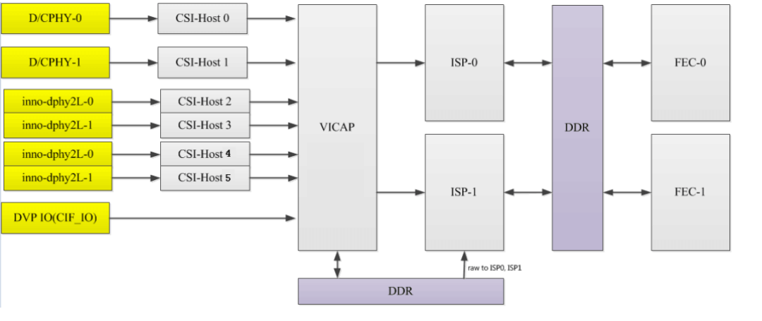
The RK3588 supports 2 ISP hardware modules, and each ISP device can virtualize multiple virtual nodes. The software reads the image data from DDR for each path in turn and processes it through the ISP. For multi-camera solutions, it is recommended to evenly distribute the data flow to the two ISPs.
Readback: refers to the data being collected into DDR after going through VICAP, and after the application obtains the data, the buffer address is pushed to the ISP, and then the ISP obtains the image data from DDR.
11.3 RK3588 Camera Path:
Multi-sensor Support:
- A single hardware ISP supports up to 4 multiplexed paths, and the supported resolutions for ISP multiplexing are as follows:
- 2 paths multiplexed: maximum resolution 3840x2160, DTS corresponding configuration 2 rkisp_vir devices.
- 3 or 4 paths multiplexed: maximum resolution 2560x1536, DTS corresponding configuration 3 or 4 rkisp_vir devices.
- The hardware supports collecting up to 7 sensor paths: 6 MIPI + 1 DVP, and the software path for multiple sensors is as follows:
The following diagram shows the RK3588 camera connection link, which can support up to 7 cameras.
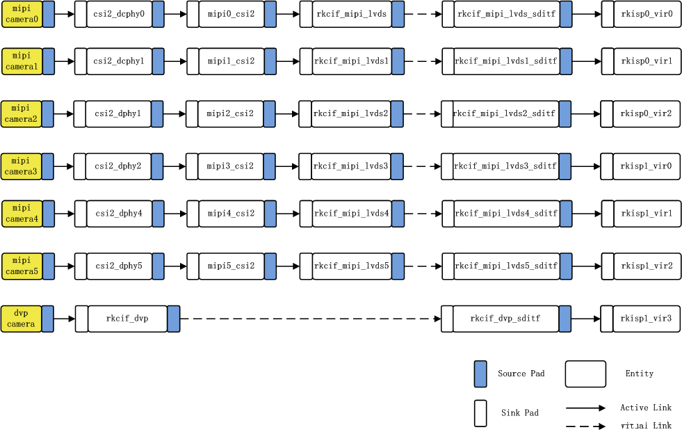
11.4 Link Analysis:

In the figure: mipi camera2---> csi2_dphy1 ---> mipi2_csi2 ---> rkcif_mipi_lvds2--->rkcif_mipi_lvds2_sditf --->rkisp0_vir2
Corresponding node: imx415 ---> csi2_dphy0 ---> mipi2_csi2 ---> rkcif_mipi_lvds2--->rkcif_mipi_lvds2_sditf --->rkisp0_vir2
Link relationship: sensor---> csi2 dphy---->mipi csi host--->vicap
Solid link analysis: Camera sensor ---> dphy ---> mipi_csi2 module parses mipi protocol ---> vicap ( rkcif node represents vicap )
Dashed link analysis: vicap ---> rkcif_mipi_lvds2_sditf ---> isp
The link relationship between each vicap node and the ISP is indicated by the XXX_sditf node that is virtually created to correspond to that relationship.
11.5 Check Camera Information
11.5.1 Check if Camera is Mounted on the I2C Bus
root@armsom:/# i2cdetect -y 5
     0  1  2  3  4  5  6  7  8  9  a  b  c  d  e  f
00:                         -- -- -- -- -- -- -- --
10: UU -- -- -- -- -- -- -- -- -- -- -- -- -- -- --
20: -- -- -- -- -- -- -- -- -- -- -- -- -- -- -- --
30: -- -- -- -- -- -- -- -- -- -- -- -- -- -- -- --
40: -- -- -- -- -- -- -- -- -- -- -- -- -- -- -- --
50: -- -- -- -- -- -- -- -- -- -- -- -- -- -- -- --
60: -- -- -- -- -- -- -- -- -- -- -- -- -- -- -- --
70: -- -- -- -- -- -- -- --
11.5.2 Check Topology
root@armsom:/home/armsom# media-ctl -d /dev/media0 -p
11.5.3 Check Files in Sys Filesystem
The kernel assigns device information description files for the camera in the /sys/class/video4linux directory.
armsom@armsom:~$ grep ov13850 /sys/class/video4linux/v*/name
/sys/class/video4linux/v4l-subdev2/name:m00_b_ov13850 5-0010
Find the Camera's corresponding video node:
armsom@armsom:~$ grep "" /sys/class/video4linux/v*/name | grep mainpath
/sys/class/video4linux/video22/name:rkisp_mainpath
/sys/class/video4linux/video31/name:rkisp_mainpath
In the ArmSoM-Sige5, the dual-camera nodes are: video22 and video31.
11.5.4 Find All Camera Devices
armsom@armsom:~$ v4l2-ctl --list-devices
rkisp-statistics (platform: rkisp):
        /dev/video29
        /dev/video30
        /dev/video38
        /dev/video39

rkcif-mipi-lvds2 (platform:rkcif):
        /dev/media0
        /dev/media1

rkcif (platform:rkcif-mipi-lvds2):
        /dev/video0
        /dev/video1
        /dev/video2
        /dev/video3
        /dev/video4
        /dev/video5
        /dev/video6
        /dev/video7
        /dev/video8
        /dev/video9
        /dev/video10

rkcif (platform:rkcif-mipi-lvds4):
        /dev/video11
        /dev/video12
        /dev/video13
        /dev/video14
        /dev/video15
        /dev/video16


        /dev/video17
        /dev/video18
        /dev/video19
        /dev/video20
        /dev/video21

rkisp_mainpath (platform:rkisp0-vir0):
        /dev/video22
        /dev/video23
        /dev/video24
        /dev/video25
        /dev/video26
        /dev/video27
        /dev/video28
        /dev/media2

rkisp_mainpath (platform:rkisp1-vir1):
        /dev/video31
        /dev/video32
        /dev/video33
        /dev/video34
        /dev/video35
        /dev/video36
        /dev/video37
        /dev/media3
Here, /dev/video22 and /dev/video31 are the camera devices.
11.5.5 Check Supported Formats for Preview
The following is the query result of the ov13850 camera on video22 node:
root@armsom:/# v4l2-ctl -d /dev/video22 --list-formats-ext
ioctl: VIDIOC_ENUM_FMT
        Type: Video Capture Multiplanar

        [0]: 'UYVY' (UYVY 4:2:2)
                Size: Stepwise 32x32 - 2112x1568 with step 8/8
        [1]: 'NV16' (Y/UV 4:2:2)
                Size: Stepwise 32x32 - 2112x1568 with step 8/8
        [2]: 'NV61' (Y/VU 4:2:2)
                Size: Stepwise 32x32 - 2112x1568 with step 8/8
        [3]: 'NV21' (Y/VU 4:2:0)
                Size: Stepwise 32x32 - 2112x1568 with step 8/8
        [4]: 'NV12' (Y/UV 4:2:0)
                Size: Stepwise 32x32 - 2112x1568 with step 8/8
        [5]: 'NM21' (Y/VU 4:2:0 (N-C))
                Size: Stepwise 32x32 - 2112x1568 with step 8/8
        [6]: 'NM12' (Y/UV 4:2:0 (N-C))
                Size: Stepwise 32x32 - 2112x1568 with step 8/8
11.5.6 View All Device Information
root@armsom:/# v4l2-ctl --all --device /dev/video22
Driver Info:
        Driver name      : rkisp_v10
        Card type        : rkisp_mainpath
        Bus info         : platform:rkisp-vir1
        Driver version   : 2.9.0
        Capabilities     : 0x84201000
                Video Capture Multiplanar
                Streaming
                Extended Pix Format
                Device Capabilities
        Device Caps      : 0x04201000
                Video Capture Multiplanar
                Streaming
                Extended Pix Format
Media Driver Info:
        Driver name      : rkisp-vir1
        Model            : rkisp0
        Serial           :
        Bus info         : platform:rkisp-vir1
        Media version    : 6.1.99
        Hardware revision: 0x00000000 (0)
        Driver version   : 6.1.99
Interface Info:
        ID               : 0x03000007
        Type             : V4L Video
Entity Info:
        ID               : 0x00000006 (6)
        Name             : rkisp_mainpath
        Function         : V4L2 I/O
        Pad 0x01000009   : 0: Sink
          Link 0x0200000a: from remote pad 0x1000004 of entity 'rkisp-isp-subdev' (Unknown V4L2 Sub-Device): Data, Enabled
Priority: 2
Format Video Capture Multiplanar:
        Width/Height      : 2112/1568
        Pixel Format      : 'NV12' (Y/UV 4:2:0)
        Field             : None
        Number of planes  : 1
        Flags             :
        Colorspace        : Default
        Transfer Function : Default
        YCbCr/HSV Encoding: Default
        Quantization      : Full Range
        Plane 0           :
           Bytes per Line : 2112
           Size Image     : 4967424
Selection Video Capture: crop, Left 0, Top 0, Width 2112, Height 1568, Flags:
Selection Video Capture: crop_bounds, Left 0, Top 0, Width 2112, Height 1568, Flags:
Selection Video Output: crop, Left 0, Top 0, Width 2112, Height 1568, Flags:
Selection Video Output: crop_bounds, Left 0, Top 0, Width 2112, Height 1568, Flags:

Image Processing Controls

                     pixel_rate 0x009f0902 (int64)  : min=0 max=1000000000 step=1 default=1000000000 value=120000000 flags=read-only, volatile
11.5.7 Switch to other resolutions
OV13850 supports multiple resolutions of output, default is 2112/1568. Now change the output resolution to 4224x3136.
media-ctl -d /dev/media0 --set-v4l2 '"m00_b_ov13850 5-0010":0[fmt:SBGGR10_1X10/4224x3136]'
media-ctl -d /dev/media2 --set-v4l2 '"rkcif-mipi-lvds1":0[fmt:SBGGR10_1X10/4224x3136]'
Other resolutions can also be set in the same way as above
11.5.8 Camera capture
In ArmSoM Sige7, the preview command for Camera is:
- Start the RKAIQ 3A service:
systemctl restart rkaiq_3A.service
- screenshot:
v4l2-ctl -d /dev/video22 --set-fmt-video=width=2112,height=1568,pixelformat=NV12 --stream-mmap=3 --stream-skip=30 --stream-to=/mnt/output.yuv --stream-count=1 --stream-poll
This way, you can use ISP to process the yuv file with good results
11.6 Preview camera
The following command formats, resolutions, and frame rates can be modified according to actual needs:
gst-launch-1.0 v4l2src device=/dev/video22 ! \
    video/x-raw,format=NV12,width=2112,height=1568,framerate=30/1 ! \
    videoconvert ! \
    autovideosink

gst-launch-1.0 v4l2src device=/dev/video31 ! \
    video/x-raw,format=NV12,width=2112,height=1568,framerate=30/1 ! \
    videoconvert ! \
    autovideosink
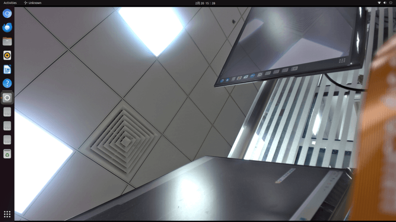
11.7 Camera Application Development
Customers can develop camera-related applications according to their needs. Below is an example of a dual-camera application developed using QT:
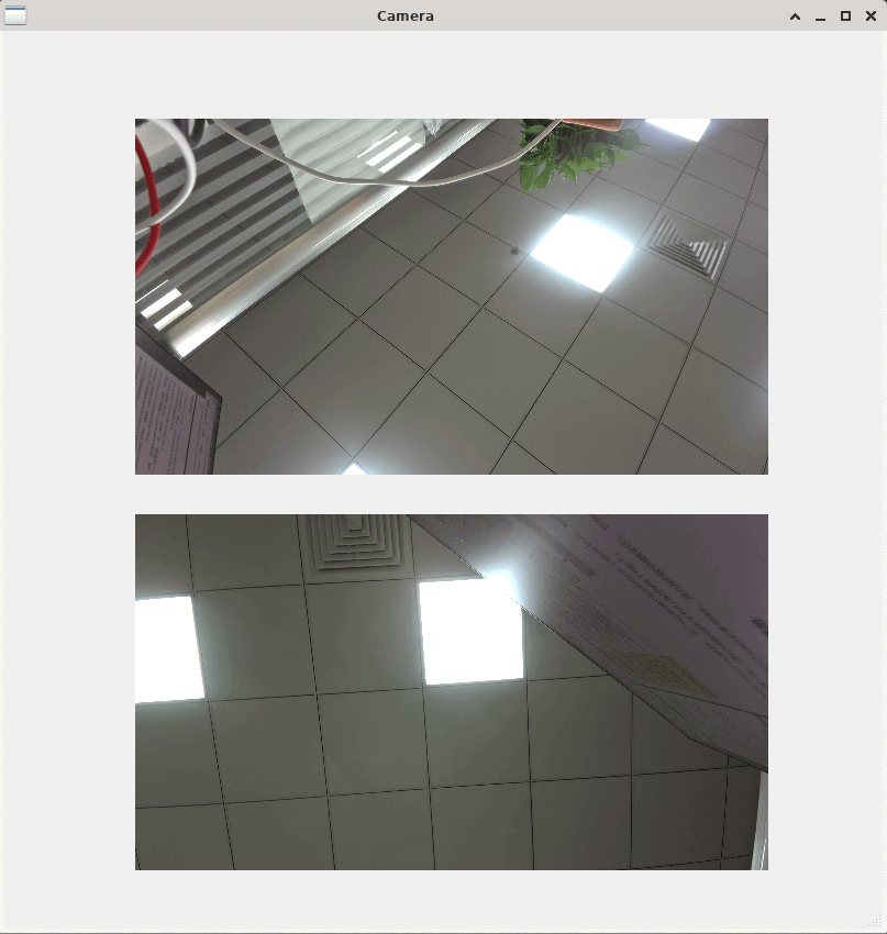
Currently, the Armbian system does not support 3A services, so ISP correction for camera image calibration cannot be activated. Customers who require camera functionality can use the Debian system, which is officially supported by Rockchip. If a camera is not supported by Debian, customers can contact ArmSoM official support for assistance.